Hello everyone,
This is my first post on the forum and there will be many more since I have four Spectrum comps that I intend to repair. I'll start with model 4B. First, I checked the 4116 chips and saw that they lost -5V and +12V. Ceramic capacitors C1-C4 show 0.35V, the voltage on C44 and C45 is 2.8V, while C46, C60, and C80 get 12V. There's no voltage on capacitor C79. TR4 gets 12V on the first pin. IC14 pin 1 receives 1.85V, pins 2, 3, and 4 receive 4V each, pin 16 receives 2.8V.
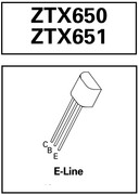
Most likely TR4 (ZTX650) has died. A ZTX651 or a ZTX653 can be used as a replacement. It's also possible that TR5 has died.
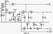
The most common causes of TR4 becoming damaged are edge-connector abuse (expansion/interface being removed or fitted while the computer is powered on or other short circuit), one or more faulty "lower" DRAM chips ( IC6 to IC13, type 4116 or equivalent) or a failure of one (or more) of the electrolytic capacitors in the DC/DC converter part of the power supply circuitry that TR4 is part of.
Please note that the +9V (nominal) input from the PSU may rise to anywhere between 10V and 13V as it's an unregulated type. The +12V supply to the "lower" DRAM and the video section is derived from this, but is not the same supply.
Also, without a -5V supply, at the same time that one or both positive supplies (+5V and +12V) are present, 4116 DRAM chips may suffer internal damage. So only power up for short periods of time, just long enough to carry out a test.
Mark
Standby alert
“There are four lights!”
Step up to red alert. Sir, are you absolutely sure? It does mean changing the bulb
Looking forward to summer being good this year.
Hello Mark. Thank you for the advice. I've checked TR4, it shows me that there is zero voltage on the first pin, while pins 2 and 3 show 12V. Interestingly, at one point, my multimeter showed 9.7V on C79 with a beep. After that, it again showed 0V. Could there be a problem with it?
An addition to the previous post: As I was using an automatic multimeter, I didn't immediately notice that it switched to resistance measurement mode, so the measurement of capacitor C79 showed a resistance of 110 kOhm on the negative side, while on the positive side it showed 9.7 Ohm, not 9.7 volts. As I mentioned, a beep signal is heard during this process.
TR4 is a bipolar NPN transistor, so it’s more useful to refer to the three terminals/leads by the junction names:
c - collector,
b - base,
e - emitter.
In this circuit (TR4), the emitter is connected to the 0V/GND/ground rail, so no need to test the voltage at this point.
The voltage on the base is supposed to be a pulsating waveform, during normal operation it should not have a DC voltage as high as 12V on it.
The collector is connected to one winding of “the coil” which in turn is connected to the (nominal) +9V rail. This is the input from the mains power supply unit (PSU) (also called a mains adapter). As the mains PSU is an unregulated type, the output voltage will vary depending on how much power the load (the computer) is using. Hence the voltage from it can be as high as 13V (with no load).
During normal operation, as the transistor switches on in response to the waveform at its base, the voltage at the collector will also be a pulsating waveform. It should not be a steady +12V.
Note that be very careful when using an automatic meter. In complex circuits, they can get confused and show an invalid result. When a circuit is powered, in general, any resistance measurement is invalid.
Mark
Standby alert
“There are four lights!”
Step up to red alert. Sir, are you absolutely sure? It does mean changing the bulb
Looking forward to summer being good this year.
OK, I'll use the ECB markings from now on. So, E is 0, while C and B are slightly over 12V. The question arises: what could have caused such a high voltage at the base? I'm not an expert at reading schematics, but from what I can see, it's connected to the coil, and in front of it is resistor R61.
I changed C79 and installed a new capacitor (radial, as I didn't have another), but the symptoms remained the same. After that, I measured the capacitance of the removed capacitor and it showed a value of 1.17uF. Obviously, there is something else at play
TR4 base acts as a silicon semiconductor junction. The turn on voltage is just over 0.5V (measured between the base and emitter terminals) and depending on the circuit, it could go a bit higher. You should however, never see a voltage here much above 1V.
This is a complex circuit. TR4 when working normally is a type of oscillator. The base voltage and current being controlled by two things. Firstly, via TR5, R60, and R61. And secondly, via magnetic feedback from one winding (the side connected to TR4 collector) of "the coil" to the other winding of "the coil".
Resistors R59 and R58 form a voltage divider. If the +12V rail is exactly 12V, then the junction of R59, R58, C74 and TR5 base will be 4.285V.
TR5 emitter is actually connected to the +5V rail (the schematic is wrong).
TR5 therefore is comparing the voltage on its base (plus the 0.6V to 0.7V junction voltage) to its emitter voltage. If the +12V rail voltage is too low, TR5 turns on more and a higher voltage and higher current flows to TR4 base via TR5 collector, R60, R61 and the coil. The oscillations of TR4 are therefore more powerful. More energy is transferred to C44 (via C80 and D15) and hence the voltage on the +12V rail increases.
If the +12V rail voltage is too high, TR5 turns on less and a lower voltage and lower current flows to TR4 base via TR5 collector, R60, R61 and the coil.
Hence this circuit tries to maintain the +12V rail at a nearly constant and steady voltage.
Typically if TR4 base is at the same voltage as its collector, its been destroyed. The base-collector is short circuit and the emitter is internally open circuit.
I recommend that C44 (100µF), C45 (100µF), C46 (1µF), C74 (4.7µF), C79 (1µF)(which you have already done), C80 (22µF) are renewed plus a new transistor is fitted in TR4 position. Once done, hold your finger on TR4 and monitor the voltage on the +12V rail. If TR4 gets hot, switch off at once. But note the voltage that your meter was showing.
Mark
Standby alert
“There are four lights!”
Step up to red alert. Sir, are you absolutely sure? It does mean changing the bulb
Looking forward to summer being good this year.
It turned out much simpler than I expected. It was enough to change TR4, and everything worked perfectly. Many thanks for your help, Mark. The only thing that's a bit unclear to me from your previous post is the detail in the 12V voltage divider, since according to the schematic, R50 and R59 have a value of 1K, then the voltage at the output should be: Vout = 12V * 1KΩ / (1KΩ + 1KΩ) = 6V. How did we then get to 4.285V?
Since we've finished with the first "patient", I'll open another topic, this time it's about the Issue 4A model. Once again, many thanks for your help!
Because there are numerous errors on the schematics for the various different issue boards, I normally compare one with another. And/or check the service manual. R59 is specified as a 2% tolerance 1.8k resistor. This may not be clear on some diagrams.
Good to know that this board is now working
Mark
Standby alert
“There are four lights!”
Step up to red alert. Sir, are you absolutely sure? It does mean changing the bulb
Looking forward to summer being good this year.
It’s better to have a separate thread for each fault so that there is no confusion.
Based on the voltages you have posted, TR5 is fully “on” because the +12V rail is low, this is correct. TR4 appears to also fully on (it should not be continuously fully on). Or there is a short circuit to 0V/GND. Or no current is getting to the collector (hence 0V). Do you have approximately 9V to 12V at the supply side of the coil? What voltage do you get on the coil at the TR4 collector end of it?
With the power off, what resistance is this winding of the coil showing as on your multimeter?
Mark
Standby alert
“There are four lights!”
Step up to red alert. Sir, are you absolutely sure? It does mean changing the bulb
Looking forward to summer being good this year.
Resistance on the coil is ~0.01 to 0.01 ohms, I think it's ok, I get 9v in the correct places. I think the other side of the coil is 0.7v
I've done the Dc-Dc mod and replaced all the electrolytic caps in the power circuit but that hasn't fixed anything. I now believe that C77 & C49 are destroyed as I can't measure any resistance over them, multimeter thinks there's no connection. I'm going to replace those once the parts arrive and if it's still not working I'll start a new thread.
C77 and C49 are small value capacitors and are fairly robust electrically speaking. If they show no signs of physical damage, they are likely okay. However, C43 is critical to the operation of TR4.
Mark
Last edited by 1024MAK on Tue May 28, 2024 12:15 pm, edited 1 time in total.
Standby alert
“There are four lights!”
Step up to red alert. Sir, are you absolutely sure? It does mean changing the bulb
Looking forward to summer being good this year.
Do you have a recommendation for which value cap to use at C49? I currently have a 560pf but the service manual suggests that either 560pf or 47nf are OK.
See my blog page for the values for the final Sinclair modification.
Note that the schematic on this page shows both the original configuration and the new positions of the changed and new components. Read the notes to understand the diagram.
C49 should be 560pF.
C77 should be removed if the circuit has been upgraded to the configuration shown on my blog page.
It’s worthwhile going through the schematic and testing that each node is correct. That is for each circuit junction (node), all the correct components do indeed connect to the node. This then should prove that there are no open circuit faults. And no incorrect connections.
Mark
Standby alert
“There are four lights!”
Step up to red alert. Sir, are you absolutely sure? It does mean changing the bulb
Looking forward to summer being good this year.