Look at the video below. JoulesperCoulomb shows the way you can test transistors. He do it on Tr4 Tr5 that is for dc converter. Do the same test on TR1,TR2,TR8,TR9 and post the results here.
[media]https://m.youtube.com/watch?v=IzgCmldm2H4&t=33s[/media]
Issue 4A with no colour!
-
Muttley Black

- Microbot
- Posts: 119
- Joined: Wed Apr 03, 2019 3:31 pm
Re: Issue 4A with no colour!
You change the TR1 & TR2 with BC549C just to give more brightness to your screen, am I right? If yes, that’s mean that you still got the 2x ZTX313 and they are in working order. Have you tried to put them back and see the results?
LET REPLY$="OFF-TOPIC"
PRINT COMIC$="GREAT"

-
Liveinabin

- Drutt
- Posts: 25
- Joined: Sun May 05, 2019 6:23 pm
- Location: Ipswich
- Contact:
Re: Issue 4A with no colour!
Superb video. Thanks. I'm getting around .7v on those transistors so, according to that guide, they check out, yes?Muttley Black wrote: ↑Sun May 05, 2019 10:17 pm Look at the video below. JoulesperCoulomb shows the way you can test transistors. He do it on Tr4 Tr5 that is for dc converter. Do the same test on TR1,TR2,TR8,TR9 and post the results here.
One alarming thing. Early in that video, there is a test for the voltage regulator. Should give a reading of >100 kOhms. I get 76.
Last edited by Liveinabin on Sun May 05, 2019 11:10 pm, edited 1 time in total.
-
Liveinabin
- Drutt
- Posts: 25
- Joined: Sun May 05, 2019 6:23 pm
- Location: Ipswich
- Contact:
-
Liveinabin
- Drutt
- Posts: 25
- Joined: Sun May 05, 2019 6:23 pm
- Location: Ipswich
- Contact:
Re: Issue 4A with no colour!
Sorry, just spotted this. Um, no. I changed them a couple of weeks ago and stupidly didn't keep the bits. I do have 4 more unused BC549Cs and a single (new) ZTX313 but I could easily pick up more if you think it's worth try. They're not expensiveMuttley Black wrote: ↑Sun May 05, 2019 10:45 pm You change the TR1 & TR2 with BC549C just to give more brightness to your screen, am I right? If yes, that’s mean that you still got the 2x ZTX313 and they are in working order. Have you tried to put them back and see the results?
-
Muttley Black
- Microbot
- Posts: 119
- Joined: Wed Apr 03, 2019 3:31 pm
Re: Issue 4A with no colour!
Basically, this video talking about some test we need to do before switch on a ZX Spectrum. Mostly because the most common problem on ZX's are the transistors TR4 /TR5 that was used on dc circuit to provide the -5volt & +12volt that 4116 lower ram need. Missing the -5 volt can easily blow away all the 4116 ram. In the other hand a faulty 4116 ram can easily blow TR4 transistor. But all this is not part of your story. Anyway, is always good to test the voltages on your ZX just to be sure about them. Pins 1,8,9,16 of any 4116 ram can give you this results. About 7805 voltage regulator, the only thing it does is to convert the (about) 9volt to 5volt.
Now about transistor test, you need to do them with your multimeter set on "diode test". See the test on the video carefully. You should post 4 measurements for every transistor.
Now about transistor test, you need to do them with your multimeter set on "diode test". See the test on the video carefully. You should post 4 measurements for every transistor.
-
Liveinabin
- Drutt
- Posts: 25
- Joined: Sun May 05, 2019 6:23 pm
- Location: Ipswich
- Contact:
Re: Issue 4A with no colour!
Oh right, of course. I’ll post results tomorrow. Thanks for all of your help tonight. Sorry to take up so much of your Sunday evening 

-
Liveinabin
- Drutt
- Posts: 25
- Joined: Sun May 05, 2019 6:23 pm
- Location: Ipswich
- Contact:
Re: Issue 4A with no colour!
Readings taken (I am learning a LOT about electronics here)
Four readings for each:
pos at base
1) neg at collector
2) neg at emitter
neg at base
3) pos at collector
4) pos at emitter
TR1 (BC549C)
0.63
0.70
1.73
1.68
TR2 (BC549C)
0.70
0.70
1.19
1.30
TR8 (BC184)
0.75
0.75
open
open
TR9 (BC184)
0.75
0.75
open
open
Four readings for each:
pos at base
1) neg at collector
2) neg at emitter
neg at base
3) pos at collector
4) pos at emitter
TR1 (BC549C)
0.63
0.70
1.73
1.68
TR2 (BC549C)
0.70
0.70
1.19
1.30
TR8 (BC184)
0.75
0.75
open
open
TR9 (BC184)
0.75
0.75
open
open
-
Muttley Black
- Microbot
- Posts: 119
- Joined: Wed Apr 03, 2019 3:31 pm
Re: Issue 4A with no colour!
TR1 looks faulty to me. Cause with neg at base, you should get "open", both on collector and emitter if i am not mistaken. If you are sure that you measure TR1 as TR1 and TR2 as TR2 then replace TR1. I say that because your TR1 measurements fit more to TR2 transistor. Anyway, to be 100% sure replace both TR1 & TR2 with new BC549C transistors and tell as if the problem solved. The other transistors looks ok.
Also post your voltages just to have a picture about them. With neg probe to ground measure voltages on pins 1,8,9 and 16 from the IC6 and post them here.
Also post your voltages just to have a picture about them. With neg probe to ground measure voltages on pins 1,8,9 and 16 from the IC6 and post them here.
-
1024MAK

- Bugaboo
- Posts: 3118
- Joined: Wed Nov 15, 2017 2:52 pm
- Location: Sunny Somerset in the U.K. in Europe
Re: Issue 4A with no colour!
Yeah, but keep in mind that with any in-circuit testing, the results may be affected by the other components on the board.
Mark
Mark
“There are four lights!”
Step up to red alert. Sir, are you absolutely sure? It does mean changing the bulb
Looking forward to summer later in the year.
-
Muttley Black
- Microbot
- Posts: 119
- Joined: Wed Apr 03, 2019 3:31 pm
Re: Issue 4A with no colour!
That's true. But TR1 should give you this measurements ("open", both on collector and emitter with neg at base) in-circuit testing. I also test it on my spectrum's after your post.
-
Liveinabin
- Drutt
- Posts: 25
- Joined: Sun May 05, 2019 6:23 pm
- Location: Ipswich
- Contact:
Re: Issue 4A with no colour!
I’ll check my measurements again and I’ll change both components (it’ll be a good chance to have a proper look at the tracks as make sure I haven’t shorted/damaged anything). I’ll report back tomorrow night with findings and more readings.Muttley Black wrote: ↑Mon May 06, 2019 9:40 pm TR1 looks faulty to me. Cause with neg at base, you should get "open", both on collector and emitter if i am not mistaken. If you are sure that you measure TR1 as TR1 and TR2 as TR2 then replace TR1. I say that because your TR1 measurements fit more to TR2 transistor. Anyway, to be 100% sure replace both TR1 & TR2 with new BC549C transistors and tell as if the problem solved. The other transistors looks ok.
Also post your voltages just to have a picture about them. With neg probe to ground measure voltages on pins 1,8,9 and 16 from the IC6 and post them here.
Thanks so much for helping me out here. Really appreciate it.
-
1024MAK
- Bugaboo
- Posts: 3118
- Joined: Wed Nov 15, 2017 2:52 pm
- Location: Sunny Somerset in the U.K. in Europe
Re: Issue 4A with no colour!
If you are getting a good monochrome picture. By that I mean good contrast and brightness, then there can’t be much wrong with TR1 and TR2, as the monochrome (‘luminance’) signal passes through both of these.
Also TR1 has nothing to do with the colour part of the signal. The encoded colour signal comes from pin 13 of IC14 (LM1889) via C65 (100nF) to TR2 base, where it is mixed with the ‘luminance’ signal.
An oscilloscope would be a great help with fault finding this problem.
Mark
Also TR1 has nothing to do with the colour part of the signal. The encoded colour signal comes from pin 13 of IC14 (LM1889) via C65 (100nF) to TR2 base, where it is mixed with the ‘luminance’ signal.
An oscilloscope would be a great help with fault finding this problem.
Mark
“There are four lights!”
Step up to red alert. Sir, are you absolutely sure? It does mean changing the bulb
Looking forward to summer later in the year.
-
Liveinabin
- Drutt
- Posts: 25
- Joined: Sun May 05, 2019 6:23 pm
- Location: Ipswich
- Contact:
Re: Issue 4A with no colour!
The mono image is perfectly fine (well, for a Spectrum).
-
1024MAK
- Bugaboo
- Posts: 3118
- Joined: Wed Nov 15, 2017 2:52 pm
- Location: Sunny Somerset in the U.K. in Europe
Re: Issue 4A with no colour!
So, some questions.
First, have you used a magnifying glass to carefully visually examine the areas of the video section where you did any work. Both on the top side of the board and on the underside of the board. Do this under a good bright light, or better still, in good daylight. You are looking for any of the following: cracks or breaks in the PCB tracks/pads, dry solder joints (cracked, distorted, discoloured, dull), solder splashes (including thin solder threads, balls of solder stuck in flux), components fitted the wrong way round, components where a leg has been fitted in the wrong hole.
Tell me about the display/monitor/TV that you are using. Did this Spectrum work okay before with it? Have you tried this Spectrum on another display/monitor/TV? Does this display/monitor/TV work okay with other 8 bit computers?
I understand that you have a digital multimeter. Tell me about your digital multimeter. Does it have a frequency range? Does it have a 200mV AC range?
Do you have any other test gear?
Do you have another ZX Spectrum? If yes, which model?
Mark
“There are four lights!”
Step up to red alert. Sir, are you absolutely sure? It does mean changing the bulb
Looking forward to summer later in the year.
-
Muttley Black
- Microbot
- Posts: 119
- Joined: Wed Apr 03, 2019 3:31 pm
Re: Issue 4A with no colour!
All this "transistors" story happens because [mention]Ast A. Moore[/mention] ask him to test the transistors and friend didn't know the way to do it. So i drive him to JoulesperCoulomb video that shows the way. After that, he post the measurements and we found out a faulty transistor. For sure the first suspect for missing color is the LM1889 but we cant ignore the fact that is a faulty transistor on the board.
Anyway. I've been here, on this forum not much time, but for a reason. i have read ALL threads on hardware category and what i want to say is that both [mention]1024MAK[/mention] and [mention]Ast A. Moore[/mention] can be easily named "ZX Resurrectors". And it is not only that. They are both very well technical educated members of this forum and they are always happy to help. So you are in good hands my friend.
Anyway. I've been here, on this forum not much time, but for a reason. i have read ALL threads on hardware category and what i want to say is that both [mention]1024MAK[/mention] and [mention]Ast A. Moore[/mention] can be easily named "ZX Resurrectors". And it is not only that. They are both very well technical educated members of this forum and they are always happy to help. So you are in good hands my friend.
-
Ast A. Moore

- Rick Dangerous
- Posts: 2641
- Joined: Mon Nov 13, 2017 3:16 pm
Re: Issue 4A with no colour!
Aww, thanks, Muttley, but Mark is by far much more knowledgeable in this area than I am.
Every man should plant a tree, build a house, and write a ZX Spectrum game.
Author of A Yankee in Iraq, a 50 fps shoot-’em-up—the first game to utilize the floating bus on the +2A/+3,
and zasm Z80 Assembler syntax highlighter.
Author of A Yankee in Iraq, a 50 fps shoot-’em-up—the first game to utilize the floating bus on the +2A/+3,
and zasm Z80 Assembler syntax highlighter.
-
Liveinabin
- Drutt
- Posts: 25
- Joined: Sun May 05, 2019 6:23 pm
- Location: Ipswich
- Contact:
Re: Issue 4A with no colour!
Thank you all. I’ll try and get some time tonight/poss tomorrow to go over the Spectrum carefully.
-
Liveinabin
- Drutt
- Posts: 25
- Joined: Sun May 05, 2019 6:23 pm
- Location: Ipswich
- Contact:
Re: Issue 4A with no colour!
I’m busy with the magnifying glass right now. Aside from a tiny bit of messiness around TR1 and TR2 caused when desoldering them, I can’t see anything else..yet. I will desolder those transistors (carefully) to get a better look at the board underneath.1024MAK wrote: ↑Tue May 07, 2019 9:17 am So, some questions.
First, have you used a magnifying glass to carefully visually examine the areas of the video section where you did any work. Both on the top side of the board and on the underside of the board. Do this under a good bright light, or better still, in good daylight. You are looking for any of the following: cracks or breaks in the PCB tracks/pads, dry solder joints (cracked, distorted, discoloured, dull), solder splashes (including thin solder threads, balls of solder stuck in flux), components fitted the wrong way round, components where a leg has been fitted in the wrong hole.
Tell me about the display/monitor/TV that you are using. Did this Spectrum work okay before with it? Have you tried this Spectrum on another display/monitor/TV? Does this display/monitor/TV work okay with other 8 bit computers?
I understand that you have a digital multimeter. Tell me about your digital multimeter. Does it have a frequency range? Does it have a 200mV AC range?
Do you have any other test gear?
Do you have another ZX Spectrum? If yes, which model?
Mark
My monitor is an LG 24” LCD. I use it as it runs everything; the RF input likes ZX81s and Spectrums (and even Fairchild channel F and old pong machines) and the composite input is happy enough with everything else. It’s been fine with my other Spectrum’s (both now composite modded) and it liked this busted one back when it was RF.
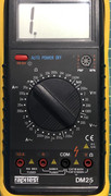
I attached a picture of my multimeter.
As for other test equipment. Sadly no. I understand an oscilloscope would be a benefit but aren’t they astronomically expensive for a hobbyist? If there’s a halfway affordable model, I’ll happily pick one up.
As for other Spectrums. I have 2 more. An issue one 16K and a Samsung 3B 48K
-
Muttley Black
- Microbot
- Posts: 119
- Joined: Wed Apr 03, 2019 3:31 pm
-
Ast A. Moore
- Rick Dangerous
- Posts: 2641
- Joined: Mon Nov 13, 2017 3:16 pm
Re: Issue 4A with no colour!
For an analog scope, I’d say at least 20–40 MHz of bandwidth. If you’re looking at a digital scope, you’ll need something like 50–100 MHz of bandwidth with 200 MS/s and enough memory depth.
A two-channel scope is often beneficial, but even a single-channel scope will do the job nicely.
An aftermarket analog scope can be obtained dirt cheap and is a pleasure to use. If it works, that is. You might end up with something you’ll spend more time repairing than working with.
Cheap digital scopes have gotten better, but decent ones can still be quite pricey and take a little getting used to.
Every man should plant a tree, build a house, and write a ZX Spectrum game.
Author of A Yankee in Iraq, a 50 fps shoot-’em-up—the first game to utilize the floating bus on the +2A/+3,
and zasm Z80 Assembler syntax highlighter.
Author of A Yankee in Iraq, a 50 fps shoot-’em-up—the first game to utilize the floating bus on the +2A/+3,
and zasm Z80 Assembler syntax highlighter.
-
Liveinabin
- Drutt
- Posts: 25
- Joined: Sun May 05, 2019 6:23 pm
- Location: Ipswich
- Contact:
Re: Issue 4A with no colour!
So given that I'm currently bereft of any other test equipment; am I right in assuming the component we really needed to test was the LM1889 video encoder chip (as I'm figuring that it is responsible for the colour, mostly)?
Reason I ask is, I'm about to order some bits anyway (keyboard membrane, voltage regulator..) and a new LM1889 is only £3. If we're even vaguely suspicious about the chip, I'll happily pay £3 to find out
Reason I ask is, I'm about to order some bits anyway (keyboard membrane, voltage regulator..) and a new LM1889 is only £3. If we're even vaguely suspicious about the chip, I'll happily pay £3 to find out
-
Ast A. Moore
- Rick Dangerous
- Posts: 2641
- Joined: Mon Nov 13, 2017 3:16 pm
Re: Issue 4A with no colour!
In that case, go for it, definitely.Liveinabin wrote: ↑Thu May 09, 2019 9:06 am If we're even vaguely suspicious about the chip, I'll happily pay £3 to find out
Every man should plant a tree, build a house, and write a ZX Spectrum game.
Author of A Yankee in Iraq, a 50 fps shoot-’em-up—the first game to utilize the floating bus on the +2A/+3,
and zasm Z80 Assembler syntax highlighter.
Author of A Yankee in Iraq, a 50 fps shoot-’em-up—the first game to utilize the floating bus on the +2A/+3,
and zasm Z80 Assembler syntax highlighter.
-
1024MAK
- Bugaboo
- Posts: 3118
- Joined: Wed Nov 15, 2017 2:52 pm
- Location: Sunny Somerset in the U.K. in Europe
Re: Issue 4A with no colour!
The cheapest will be a used analogue ‘scope. I recommend one with a minimum bandwidth of 25MHz. Or higher. Ideally the analogue bandwidth should be at least ten times greater than the frequency of the signal you want to measure/see. Especially with digital waveforms that are supposed to have fast rise times, fall times and are supposed to be so called ‘square waves’ (but are actually pulses).
The best value digital ‘scopes are made by Rigol and their basic (cheaper!) models are popular amongst the home ‘retro’ computer community. The greater the sampling rate and the greater the memory, the better the resolution of the displayed signal waveform.
Note that if you do want to buy a new Rigol, buy it from an authorised dealer, as otherwise the warranty will not be valid.
Dual/two channel ‘scopes, with a separate trigger input are good. Four channel can be very useful (but cost a lot more). And if you are feeling flush with money, you can get ‘scopes that include multiple digital inputs like a logic analyser. These are known as MSO - mixed signal oscilloscopes.
As well as stand alone digital ‘scopes, there are USB PC ‘scopes. I use one from pico. These have the high frequency circuitry in a box that you connect to a PC. Then you run an application on the PC, and get a display on the PC of the signal along with a control panel. Most waveforms that I post online are from my pico. Note that despite using a PC, these are also not cheap.
In answer to your question about buying spares, yes, if you can afford it, it’s always a good idea. It’s not often that the LM1889 chip fails, they are normally reliable. I suspect one of the peripheral components or connections.
If you are buying spares, buy a new crystal for X2 (4.43361875MHz).
See the service manual for more about the sub-carrier (colour) circuitry (here).
Mark
“There are four lights!”
Step up to red alert. Sir, are you absolutely sure? It does mean changing the bulb
Looking forward to summer later in the year.