Nothing before I started mucking about with itdfzx wrote: ↑Sun May 19, 2019 10:09 amHaving quietly followed the saga for 5 pages of comments, I'm now looking forward to Mark telling us all what's wrong with the flippin' thing!Liveinabin wrote: ↑Sat May 18, 2019 5:00 pm I’m glad it’ll belong to someone who can fix it or at least revive another Spectrum with it.
Issue 4A with no colour!
-
Liveinabin

- Drutt
- Posts: 25
- Joined: Sun May 05, 2019 6:23 pm
- Location: Ipswich
- Contact:
Re: Issue 4A with no colour!
-
1024MAK

- Bugaboo
- Posts: 3123
- Joined: Wed Nov 15, 2017 2:52 pm
- Location: Sunny Somerset in the U.K. in Europe
Re: Issue 4A with no colour!
Hi
I thought you all would like an update.
I’ve found two problems.
The cause of the loss of the video output, is a broken PCB track on the underside of the board. Between transistor TR1 collector lead and resistor R51. From R51 the track goes to TR2 base. Hence TR2 having no signal, is just turned fully on all the time due to resistor R51. Therefore there is no valid video signal going to the output socket (this machine has been composite video modified).
The cause of no colour is a missing PCB track between capacitor C65 + pad and a through-hole via under capacitor C40. This track is (well, was!) on the top side of the board. It links C65 + with R72, which in turn is linked to pin 13 of the LM1889 colour encoder chip. With this missing track, there was no way the colour video carrier signal could be mixed into the monochrome video signal.
But it appears that the system is running, as if I simulate key presses, the bleeper clicks, and if I fill up the input line, eventually I get the error rasp sound (which is BASIC saying, I’m not having that as an input!). And on my oscilloscope, I get a good video waveform at TR1 base.
So I fired up the soldering iron and set to repair these two problems.
Here’s some photos...
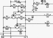
The relevant part of the schematic diagram:
The damaged track causing the loss of the video signal:
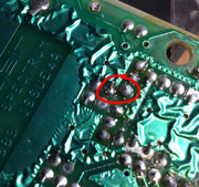
What, can’t see the break? Try this photo...

Okay, so no you can’t really see in the earlier photos. So I cleaned the old flux and dirt off the board. Now you can see the track. It does not look like it is broken. But I get intermittent continuity when I test with the multimeter.

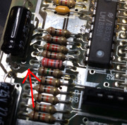
Having confirmed that the track is the problem, I desoldered the relevant solder pads ready to fit a wire to replace the track. Look at the track now:
And here is a shot showing the wire that replaces the broken track:

This is the missing track that resulted in no colour in the picture (well, the bit of the board where the track used to be, you can just see the light green line where the copper track has been lifted away):
And the fix (put on the bottom side so it does not spoil the top of the board and is easier to fit on this side anyway ):
):

A screen shot showing it now does colour (sorry, without a keyboard attached, I could only be bothered to poke wires in the keyboard sockets to type in BORDER 3)...

So as you can see, it now works okay.
When I have got a keyboard membrane to hand, I’ll do a few tests to see if it’s running as a 48K machine.
Mark
I thought you all would like an update.
I’ve found two problems.
The cause of the loss of the video output, is a broken PCB track on the underside of the board. Between transistor TR1 collector lead and resistor R51. From R51 the track goes to TR2 base. Hence TR2 having no signal, is just turned fully on all the time due to resistor R51. Therefore there is no valid video signal going to the output socket (this machine has been composite video modified).
The cause of no colour is a missing PCB track between capacitor C65 + pad and a through-hole via under capacitor C40. This track is (well, was!) on the top side of the board. It links C65 + with R72, which in turn is linked to pin 13 of the LM1889 colour encoder chip. With this missing track, there was no way the colour video carrier signal could be mixed into the monochrome video signal.
But it appears that the system is running, as if I simulate key presses, the bleeper clicks, and if I fill up the input line, eventually I get the error rasp sound (which is BASIC saying, I’m not having that as an input!). And on my oscilloscope, I get a good video waveform at TR1 base.
So I fired up the soldering iron and set to repair these two problems.
Here’s some photos...
The relevant part of the schematic diagram:
The damaged track causing the loss of the video signal:
What, can’t see the break? Try this photo...
Okay, so no you can’t really see in the earlier photos. So I cleaned the old flux and dirt off the board. Now you can see the track. It does not look like it is broken. But I get intermittent continuity when I test with the multimeter.
Having confirmed that the track is the problem, I desoldered the relevant solder pads ready to fit a wire to replace the track. Look at the track now:
And here is a shot showing the wire that replaces the broken track:
This is the missing track that resulted in no colour in the picture (well, the bit of the board where the track used to be, you can just see the light green line where the copper track has been lifted away):
And the fix (put on the bottom side so it does not spoil the top of the board and is easier to fit on this side anyway
A screen shot showing it now does colour (sorry, without a keyboard attached, I could only be bothered to poke wires in the keyboard sockets to type in BORDER 3)...
So as you can see, it now works okay.
When I have got a keyboard membrane to hand, I’ll do a few tests to see if it’s running as a 48K machine.
Mark
“There are four lights!”
Step up to red alert. Sir, are you absolutely sure? It does mean changing the bulb
Looking forward to summer later in the year.
-
Muttley Black

- Microbot
- Posts: 119
- Joined: Wed Apr 03, 2019 3:31 pm
Re: Issue 4A with no colour!
Well done Mark! 
-
Liveinabin
- Drutt
- Posts: 25
- Joined: Sun May 05, 2019 6:23 pm
- Location: Ipswich
- Contact:
Re: Issue 4A with no colour!
Superb stuff, Mark! I'd never have found that in a million years. Glad I sent it to you. It's clearly gone to a better home
Re: Issue 4A with no colour!
1024MAK wrote: ↑Tue May 07, 2019 9:17 am So, some questions.
First, have you used a magnifying glass to carefully visually examine the areas of the video section where you did any work. Both on the top side of the board and on the underside of the board. Do this under a good bright light, or better still, in good daylight. You are looking for any of the following: cracks or breaks in the PCB tracks/pads, dry solder joints (cracked, distorted, discoloured, dull), solder splashes (including thin solder threads, balls of solder stuck in flux), components fitted the wrong way round, components where a leg has been fitted in the wrong hole.
Tell me about the display/monitor/TV that you are using. Did this Spectrum work okay before with it? Have you tried this Spectrum on another display/monitor/TV? Does this display/monitor/TV work okay with other 8 bit computers?
I understand that you have a digital multimeter. Tell me about your digital multimeter. Does it have a frequency range? Does it have a 200mV AC range?
Do you have any other test gear?
Do you have another ZX Spectrum? If yes, which model?
Mark
This question probably saved me hours of troubleshooting!Have you tried this Spectrum on another display/monitor/TV?
My ZX Spectrum 3B was missing color, using a different LCD TV showed color.
Thanks Mark!