I bit off topic but, can you suggest a value for money oscilloscope? Just for spectrum repairs. What is the minimum requirements for? Thank you.
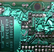
Issue 4A with no colour!
-
Ast A. Moore

- Rick Dangerous
- Posts: 2641
- Joined: Mon Nov 13, 2017 3:16 pm
Re: Issue 4A with no colour!
For an analog scope, I’d say at least 20–40 MHz of bandwidth. If you’re looking at a digital scope, you’ll need something like 50–100 MHz of bandwidth with 200 MS/s and enough memory depth.
A two-channel scope is often beneficial, but even a single-channel scope will do the job nicely.
An aftermarket analog scope can be obtained dirt cheap and is a pleasure to use. If it works, that is. You might end up with something you’ll spend more time repairing than working with.
Cheap digital scopes have gotten better, but decent ones can still be quite pricey and take a little getting used to.
Every man should plant a tree, build a house, and write a ZX Spectrum game.
Author of A Yankee in Iraq, a 50 fps shoot-’em-up—the first game to utilize the floating bus on the +2A/+3,
and zasm Z80 Assembler syntax highlighter.
Author of A Yankee in Iraq, a 50 fps shoot-’em-up—the first game to utilize the floating bus on the +2A/+3,
and zasm Z80 Assembler syntax highlighter.
-
Liveinabin

- Drutt
- Posts: 25
- Joined: Sun May 05, 2019 6:23 pm
- Location: Ipswich
- Contact:
Re: Issue 4A with no colour!
So given that I'm currently bereft of any other test equipment; am I right in assuming the component we really needed to test was the LM1889 video encoder chip (as I'm figuring that it is responsible for the colour, mostly)?
Reason I ask is, I'm about to order some bits anyway (keyboard membrane, voltage regulator..) and a new LM1889 is only £3. If we're even vaguely suspicious about the chip, I'll happily pay £3 to find out
Reason I ask is, I'm about to order some bits anyway (keyboard membrane, voltage regulator..) and a new LM1889 is only £3. If we're even vaguely suspicious about the chip, I'll happily pay £3 to find out
-
Ast A. Moore
- Rick Dangerous
- Posts: 2641
- Joined: Mon Nov 13, 2017 3:16 pm
Re: Issue 4A with no colour!
In that case, go for it, definitely.Liveinabin wrote: ↑Thu May 09, 2019 9:06 am If we're even vaguely suspicious about the chip, I'll happily pay £3 to find out
Every man should plant a tree, build a house, and write a ZX Spectrum game.
Author of A Yankee in Iraq, a 50 fps shoot-’em-up—the first game to utilize the floating bus on the +2A/+3,
and zasm Z80 Assembler syntax highlighter.
Author of A Yankee in Iraq, a 50 fps shoot-’em-up—the first game to utilize the floating bus on the +2A/+3,
and zasm Z80 Assembler syntax highlighter.
-
1024MAK

- Bugaboo
- Posts: 3118
- Joined: Wed Nov 15, 2017 2:52 pm
- Location: Sunny Somerset in the U.K. in Europe
Re: Issue 4A with no colour!
The cheapest will be a used analogue ‘scope. I recommend one with a minimum bandwidth of 25MHz. Or higher. Ideally the analogue bandwidth should be at least ten times greater than the frequency of the signal you want to measure/see. Especially with digital waveforms that are supposed to have fast rise times, fall times and are supposed to be so called ‘square waves’ (but are actually pulses).
The best value digital ‘scopes are made by Rigol and their basic (cheaper!) models are popular amongst the home ‘retro’ computer community. The greater the sampling rate and the greater the memory, the better the resolution of the displayed signal waveform.
Note that if you do want to buy a new Rigol, buy it from an authorised dealer, as otherwise the warranty will not be valid.
Dual/two channel ‘scopes, with a separate trigger input are good. Four channel can be very useful (but cost a lot more). And if you are feeling flush with money, you can get ‘scopes that include multiple digital inputs like a logic analyser. These are known as MSO - mixed signal oscilloscopes.
As well as stand alone digital ‘scopes, there are USB PC ‘scopes. I use one from pico. These have the high frequency circuitry in a box that you connect to a PC. Then you run an application on the PC, and get a display on the PC of the signal along with a control panel. Most waveforms that I post online are from my pico. Note that despite using a PC, these are also not cheap.
In answer to your question about buying spares, yes, if you can afford it, it’s always a good idea. It’s not often that the LM1889 chip fails, they are normally reliable. I suspect one of the peripheral components or connections.
If you are buying spares, buy a new crystal for X2 (4.43361875MHz).
See the service manual for more about the sub-carrier (colour) circuitry (here).
Mark
“There are four lights!”
Step up to red alert. Sir, are you absolutely sure? It does mean changing the bulb
Looking forward to summer later in the year.
-
Liveinabin
- Drutt
- Posts: 25
- Joined: Sun May 05, 2019 6:23 pm
- Location: Ipswich
- Contact:
Re: Issue 4A with no colour!
Oh yes, I forgot about the crystal. Right, all bits ordered including a matching crystal for X2 and a new LM1889 (although, as has been said, it's probably fine). About the crystal, is there a 'right' way to orient it? Do these things have a polarity?1024MAK wrote: ↑Thu May 09, 2019 10:52 am In answer to your question about buying spares, yes, if you can afford it, it’s always a good idea. It’s not often that the LM1889 chip fails, they are normally reliable. I suspect one of the peripheral components or connections.
If you are buying spares, buy a new crystal for X2 (4.43361875MHz).
See the service manual for more about the sub-carrier (colour) circuitry (here).
Mark
-
Ast A. Moore
- Rick Dangerous
- Posts: 2641
- Joined: Mon Nov 13, 2017 3:16 pm
Re: Issue 4A with no colour!
Nope, they don’t. Although, their physical orientation in space will have a small effect on their operation causing deviations form their standard frequency. (Just a technicality; no need no worry about it.)
Every man should plant a tree, build a house, and write a ZX Spectrum game.
Author of A Yankee in Iraq, a 50 fps shoot-’em-up—the first game to utilize the floating bus on the +2A/+3,
and zasm Z80 Assembler syntax highlighter.
Author of A Yankee in Iraq, a 50 fps shoot-’em-up—the first game to utilize the floating bus on the +2A/+3,
and zasm Z80 Assembler syntax highlighter.
-
Liveinabin
- Drutt
- Posts: 25
- Joined: Sun May 05, 2019 6:23 pm
- Location: Ipswich
- Contact:
Re: Issue 4A with no colour!
Oooookay! Update time.
Got a new LM1889. Fitted that. No difference (didn't think there would be but worth a pop, although desoldering that was a pain)
New crystal in X2. Still mono.
Reflowed and, in some cases resoldered and replaced some of the new capacitors around the video bit. Nope. Still greyscale.
Desoldered the BC549Cs at TR1 and TR2 (mainly to have a good look at the traces around them) and fitted new ones.
Added a 100uF transistor into the composite mod (which does indeed brighten things up)
Went over the whole board with a big magnifying glass, cleaning up as I went.
Still black and white! Gah!
I do have one more thought. I swapped TR1 and TR2 for BC549Cs at the start of this escapade (sadly ditching the old transistors) and I've tried this Spectrum on a couple of TVs: My reliable LG is greyscale and a little (also LCD) Samsung shows, it turns out, no picture at all!
Tried my other working, comp modded Spectrum on both displays (a Samsung 3B with the original TR1 TR2 transistors) and it displays on both: Well on the LG and poorly on the Samsung TV (but then the Samsung TV IS crap).
Might it just be the BC549Cs not being compatible with my TV? I read that the 'improvement' they give may not work with flat TVs. Might it be worth me fitting a couple of ZTX313s instead?
That's really all I can think of to try now.
-
1024MAK
- Bugaboo
- Posts: 3118
- Joined: Wed Nov 15, 2017 2:52 pm
- Location: Sunny Somerset in the U.K. in Europe
Re: Issue 4A with no colour!
The “monochrome” parts of the video picture require a larger bandwidth (meaning higher frequency) than the colour carrier, so as I said above, I’m not convinced. But you are free to try.
Mark
Mark
“There are four lights!”
Step up to red alert. Sir, are you absolutely sure? It does mean changing the bulb
Looking forward to summer later in the year.
-
Muttley Black

- Microbot
- Posts: 119
- Joined: Wed Apr 03, 2019 3:31 pm
Re: Issue 4A with no colour!
You have already checked if 12 volts present on LM1889 (pin14), yes?
-
Liveinabin
- Drutt
- Posts: 25
- Joined: Sun May 05, 2019 6:23 pm
- Location: Ipswich
- Contact:
Re: Issue 4A with no colour!
I’m getting 11.56vMuttley Black wrote: ↑Thu May 16, 2019 7:58 pm You have already checked if 12 volts present on LM1889 (pin14), yes?
That’s with ground probe on the plate near the voltage regulator and the positive probe on pin 14, if that’s correct.
-
1024MAK
- Bugaboo
- Posts: 3118
- Joined: Wed Nov 15, 2017 2:52 pm
- Location: Sunny Somerset in the U.K. in Europe
Re: Issue 4A with no colour!
LM1889 (IC14).
Test between pins 14 and 5.
Then between pins 15 and 5.
Then between pins 16 and 5.
Then between pins 12 and 5.
Mark
Test between pins 14 and 5.
Then between pins 15 and 5.
Then between pins 16 and 5.
Then between pins 12 and 5.
Mark
“There are four lights!”
Step up to red alert. Sir, are you absolutely sure? It does mean changing the bulb
Looking forward to summer later in the year.
-
Liveinabin
- Drutt
- Posts: 25
- Joined: Sun May 05, 2019 6:23 pm
- Location: Ipswich
- Contact:
Re: Issue 4A with no colour!
Hallo
11.58v on all of those pins.
11.58v on all of those pins.
-
Liveinabin
- Drutt
- Posts: 25
- Joined: Sun May 05, 2019 6:23 pm
- Location: Ipswich
- Contact:
Re: Issue 4A with no colour!
Ah OK, further news
Noticed that both of my Spectrums have the exact same revision of ULA so.... carefully popped both out and swapped them.
ULA from my Samsung gave no picture at all on this spectrum. ULA from this spectrum gave garbled mess on the Samsung (random block characters and colours). Checked the seating of the chips a couple of times, same thing. Swapped em back. Luckily my Samsung 3b is still fine but there's no video at all from this unit.
I dunno, reckless to try it perhaps.
SO.. I've sadly now hit my limit in the time and money I can really put into this Spectrum, and I'm sure I'm now only making things worse (even if I fixed it, still needs a new kb membrane).
Thanks SO much for your help, Mark and Muttley Black. I really appreciate it. If either of you would like a free busted Speccy to use for bits (or repair/burn for fun etc), post free, just PM me your address and I'll send it over.
I'm not done with Spectrums yet - just this one
-
1024MAK
- Bugaboo
- Posts: 3118
- Joined: Wed Nov 15, 2017 2:52 pm
- Location: Sunny Somerset in the U.K. in Europe
Re: Issue 4A with no colour!
Sorry to hear that.
Watch out for the incoming PM...
Mark
Watch out for the incoming PM...
Mark
“There are four lights!”
Step up to red alert. Sir, are you absolutely sure? It does mean changing the bulb
Looking forward to summer later in the year.
-
Liveinabin
- Drutt
- Posts: 25
- Joined: Sun May 05, 2019 6:23 pm
- Location: Ipswich
- Contact:
Re: Issue 4A with no colour!
Blimey! That was quick
Yours.
Yours.
-
1024MAK
- Bugaboo
- Posts: 3118
- Joined: Wed Nov 15, 2017 2:52 pm
- Location: Sunny Somerset in the U.K. in Europe
Re: Issue 4A with no colour!
Well, I was composing a reply just as you posted...
Mark
Mark
“There are four lights!”
Step up to red alert. Sir, are you absolutely sure? It does mean changing the bulb
Looking forward to summer later in the year.
-
Muttley Black
- Microbot
- Posts: 119
- Joined: Wed Apr 03, 2019 3:31 pm
Re: Issue 4A with no colour!
Sad.
Next time you have the same feeling, like everything is against you...just take a long break! I have four ZX Spectrum's here that need repair. Randomly i started with the "hard one". Need to finish that one, to be able to start with the other. If one day you see fireworks all over the forum, means that this day was came. And that will be the prize for the previous bad feeling.
Anyway! By sending this spectrum to Mark, means that one more spectrum will be resurrected! And that is good for all!
-
Liveinabin
- Drutt
- Posts: 25
- Joined: Sun May 05, 2019 6:23 pm
- Location: Ipswich
- Contact:
Re: Issue 4A with no colour!
That’s it exactly. I’m glad it’ll belong to someone who can fix it or at least revive another Spectrum with it.
I already have two working Spectrums (and I’ll be getting a Next when they release that) so this whole enterprise was just about getting the thing to live for it’s own sake.
The general idea was that I’d fix it while learning the basics of electronics. I’ve come to the realisation that fixing a Spectrum is probably a very bad first project as they’re very unforgiving flimsy old machines that just want to die Even with all the sage advice, I felt I was making it worse.
For what it’s worth, for karma’s sake; I’m also about to cripple a Commodore 64 as well
Thanks so much for your help, by the way. I’m certainly not done with Spectrums yet. Just that one
I already have two working Spectrums (and I’ll be getting a Next when they release that) so this whole enterprise was just about getting the thing to live for it’s own sake.
The general idea was that I’d fix it while learning the basics of electronics. I’ve come to the realisation that fixing a Spectrum is probably a very bad first project as they’re very unforgiving flimsy old machines that just want to die
For what it’s worth, for karma’s sake; I’m also about to cripple a Commodore 64 as well

Thanks so much for your help, by the way. I’m certainly not done with Spectrums yet. Just that one
Re: Issue 4A with no colour!
Having quietly followed the saga for 5 pages of comments, I'm now looking forward to Mark telling us all what's wrong with the flippin' thing!Liveinabin wrote: ↑Sat May 18, 2019 5:00 pm I’m glad it’ll belong to someone who can fix it or at least revive another Spectrum with it.
Derek Fountain, author of the ZX Spectrum C Programmer's Getting Started Guide and various open source games, hardware and other projects, including an IF1 and ZX Microdrive emulator.
-
Liveinabin
- Drutt
- Posts: 25
- Joined: Sun May 05, 2019 6:23 pm
- Location: Ipswich
- Contact:
Re: Issue 4A with no colour!
Nothing before I started mucking about with itdfzx wrote: ↑Sun May 19, 2019 10:09 amHaving quietly followed the saga for 5 pages of comments, I'm now looking forward to Mark telling us all what's wrong with the flippin' thing!Liveinabin wrote: ↑Sat May 18, 2019 5:00 pm I’m glad it’ll belong to someone who can fix it or at least revive another Spectrum with it.
-
1024MAK
- Bugaboo
- Posts: 3118
- Joined: Wed Nov 15, 2017 2:52 pm
- Location: Sunny Somerset in the U.K. in Europe
Re: Issue 4A with no colour!
Hi
I thought you all would like an update.
I’ve found two problems.
The cause of the loss of the video output, is a broken PCB track on the underside of the board. Between transistor TR1 collector lead and resistor R51. From R51 the track goes to TR2 base. Hence TR2 having no signal, is just turned fully on all the time due to resistor R51. Therefore there is no valid video signal going to the output socket (this machine has been composite video modified).
The cause of no colour is a missing PCB track between capacitor C65 + pad and a through-hole via under capacitor C40. This track is (well, was!) on the top side of the board. It links C65 + with R72, which in turn is linked to pin 13 of the LM1889 colour encoder chip. With this missing track, there was no way the colour video carrier signal could be mixed into the monochrome video signal.
But it appears that the system is running, as if I simulate key presses, the bleeper clicks, and if I fill up the input line, eventually I get the error rasp sound (which is BASIC saying, I’m not having that as an input!). And on my oscilloscope, I get a good video waveform at TR1 base.
So I fired up the soldering iron and set to repair these two problems.
Here’s some photos...
The relevant part of the schematic diagram:

The damaged track causing the loss of the video signal:
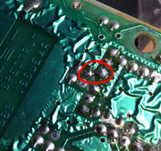
What, can’t see the break? Try this photo...

Okay, so no you can’t really see in the earlier photos. So I cleaned the old flux and dirt off the board. Now you can see the track. It does not look like it is broken. But I get intermittent continuity when I test with the multimeter.

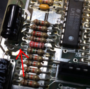
Having confirmed that the track is the problem, I desoldered the relevant solder pads ready to fit a wire to replace the track. Look at the track now:
And here is a shot showing the wire that replaces the broken track:

This is the missing track that resulted in no colour in the picture (well, the bit of the board where the track used to be, you can just see the light green line where the copper track has been lifted away):
And the fix (put on the bottom side so it does not spoil the top of the board and is easier to fit on this side anyway ):
):

A screen shot showing it now does colour (sorry, without a keyboard attached, I could only be bothered to poke wires in the keyboard sockets to type in BORDER 3)...

So as you can see, it now works okay.
When I have got a keyboard membrane to hand, I’ll do a few tests to see if it’s running as a 48K machine.
Mark
I thought you all would like an update.
I’ve found two problems.
The cause of the loss of the video output, is a broken PCB track on the underside of the board. Between transistor TR1 collector lead and resistor R51. From R51 the track goes to TR2 base. Hence TR2 having no signal, is just turned fully on all the time due to resistor R51. Therefore there is no valid video signal going to the output socket (this machine has been composite video modified).
The cause of no colour is a missing PCB track between capacitor C65 + pad and a through-hole via under capacitor C40. This track is (well, was!) on the top side of the board. It links C65 + with R72, which in turn is linked to pin 13 of the LM1889 colour encoder chip. With this missing track, there was no way the colour video carrier signal could be mixed into the monochrome video signal.
But it appears that the system is running, as if I simulate key presses, the bleeper clicks, and if I fill up the input line, eventually I get the error rasp sound (which is BASIC saying, I’m not having that as an input!). And on my oscilloscope, I get a good video waveform at TR1 base.
So I fired up the soldering iron and set to repair these two problems.
Here’s some photos...
The relevant part of the schematic diagram:
The damaged track causing the loss of the video signal:
What, can’t see the break? Try this photo...
Okay, so no you can’t really see in the earlier photos. So I cleaned the old flux and dirt off the board. Now you can see the track. It does not look like it is broken. But I get intermittent continuity when I test with the multimeter.
Having confirmed that the track is the problem, I desoldered the relevant solder pads ready to fit a wire to replace the track. Look at the track now:
And here is a shot showing the wire that replaces the broken track:
This is the missing track that resulted in no colour in the picture (well, the bit of the board where the track used to be, you can just see the light green line where the copper track has been lifted away):
And the fix (put on the bottom side so it does not spoil the top of the board and is easier to fit on this side anyway
A screen shot showing it now does colour (sorry, without a keyboard attached, I could only be bothered to poke wires in the keyboard sockets to type in BORDER 3)...
So as you can see, it now works okay.
When I have got a keyboard membrane to hand, I’ll do a few tests to see if it’s running as a 48K machine.
Mark
“There are four lights!”
Step up to red alert. Sir, are you absolutely sure? It does mean changing the bulb
Looking forward to summer later in the year.
-
Muttley Black
- Microbot
- Posts: 119
- Joined: Wed Apr 03, 2019 3:31 pm
Re: Issue 4A with no colour!
Well done Mark!
-
Liveinabin
- Drutt
- Posts: 25
- Joined: Sun May 05, 2019 6:23 pm
- Location: Ipswich
- Contact:
Re: Issue 4A with no colour!
Superb stuff, Mark! I'd never have found that in a million years. Glad I sent it to you. It's clearly gone to a better home
Re: Issue 4A with no colour!
1024MAK wrote: ↑Tue May 07, 2019 9:17 am So, some questions.
First, have you used a magnifying glass to carefully visually examine the areas of the video section where you did any work. Both on the top side of the board and on the underside of the board. Do this under a good bright light, or better still, in good daylight. You are looking for any of the following: cracks or breaks in the PCB tracks/pads, dry solder joints (cracked, distorted, discoloured, dull), solder splashes (including thin solder threads, balls of solder stuck in flux), components fitted the wrong way round, components where a leg has been fitted in the wrong hole.
Tell me about the display/monitor/TV that you are using. Did this Spectrum work okay before with it? Have you tried this Spectrum on another display/monitor/TV? Does this display/monitor/TV work okay with other 8 bit computers?
I understand that you have a digital multimeter. Tell me about your digital multimeter. Does it have a frequency range? Does it have a 200mV AC range?
Do you have any other test gear?
Do you have another ZX Spectrum? If yes, which model?
Mark
This question probably saved me hours of troubleshooting!Have you tried this Spectrum on another display/monitor/TV?
My ZX Spectrum 3B was missing color, using a different LCD TV showed color.
Thanks Mark!