
I have a 48k built into this https://www.nightfallcrew.com/10/02/201 ... -spectrum/
The worst problem seems to be the keyboard.
Most keys don't work at all.
The keyboard is made of a board at one site with 2 Cu contacts per key, which are connected by pressing down a rubber dome on them which has something which looks like graphite on it. However the resistance I could measure on the none working keys is much to high.
Anyone any idea what could be used to repair them? I know that conductive paint might do the job, but this thing is rubber. If the paint doesn't stay elastic, it might produce crumbs instead of contact.
Repairing a LO>>PROFILE professional keyboard
Repairing a LO>>PROFILE professional keyboard
"Truth would quickly cease to be stranger than fiction, once we got used to it." - H.L. Mencken

Re: Repairing a LO>>PROFILE professional keyboard
Rubber domes can be found online, for replacement.
I have some from cash register keyboards, that are identical or very similar.
I have some from cash register keyboards, that are identical or very similar.
Re: Repairing a LO>>PROFILE professional keyboard
Thanks, I'll look into that.
"Truth would quickly cease to be stranger than fiction, once we got used to it." - H.L. Mencken
Re: Repairing a LO>>PROFILE professional keyboard
Turns out, I'm mechanically incompetent. I tried to disassemble and reassemble the keyboard, but got foiled by the space bar already. I sort of reassembled it, but with only one dome and now it is all wobbly.
So I thought of an electronic substitute. the 5 date lines connected to the ULA are pulled to +5V by 10K resistors. About 100 Ohm seem to be sufficient to pull them to low, however the rubber domes seem to have degraded to 500 Ohm. So the idea is to use 5 pnp transistors, B connected to the keyboard, E connected to the corresponding input of the ULA and C connected to 0V. This should effectively divide the 500 Ohm by the factor b and so re-enable the keyboard without any need for dismounting.
Anyone any thoughts about this?
"Truth would quickly cease to be stranger than fiction, once we got used to it." - H.L. Mencken
-
1024MAK

- Bugaboo
- Posts: 3123
- Joined: Wed Nov 15, 2017 2:52 pm
- Location: Sunny Somerset in the U.K. in Europe
Re: Repairing a LO>>PROFILE professional keyboard
Don’t forget you also have to account for the B-E forward junction voltage drop/turn on voltage of the PNP transistor. The emitter will follow the base voltage minus this voltage.
So if the Z80 CPU address line goes to say 0.7V when low, then you have the forward voltage drop of diodes D1 ... D8 (one per address line), say 0.7V , then the B-E voltage, say 0.7V. That gets yo to 2.1V as the voltage the ULA will see. But it is likely to see this as a logic high
Compare that with the circuit as designed by Sinclair assuming the resistance of a set of key contacts is 500Ω. Again you have the Z80 CPU address line, say 0.7V when low, then the forward voltage drop of diodes D1 ... D8, again say 0.7V. So that’s 1.4V.
Assuming the +5V Rail is actually 5.0V, (5V - 1.4V) / (10kΩ + 500Ω ) = 0.343mA. 0.343mA through 10kΩ gives a voltage drop of 3.43V. So the ULA sees 5V - 3.43V = 1.57V.
With the same, but the resistance of a set of key contacts is 50Ω. The ULA sees 1.418V.
A much better place to put PNP transistors, is in place of diodes D1 to D8. Remove these diodes. Now connect the base of each transistor to where each diode’s cathode was (the Z80 address lines A8 ... A15). Fit additional pull-up resistors of 8.2kΩ or 10kΩ where each diode’s anode was, mount them vertically on the board. Solder the emitter of each transistor to the legs of each resistor. Common all the transistor collector legs together with some wire and connect it to a suitable 0V/GND connection. Connect the free end of the resistors to a suitable +5V/VCC connection.
Note: on some boards, there may not be room for the resistors to be mounted vertically. If the heatsink is in the way, replace the 7805 with a DC/DC converter, such as a Recom or similar
Alternatively, if there is plenty of space in the case, you can of course instead mount the PNP transistors and 5he resistors on some stripboard.
Mark
“There are four lights!”
Step up to red alert. Sir, are you absolutely sure? It does mean changing the bulb
Looking forward to summer later in the year.
Re: Repairing a LO>>PROFILE professional keyboard
Umm ... yes, that could be a problem.
I can't see how this helps my problem with increasing resistance of the key switches. I won't get less than 0V (or taking B-E into account maybe 0.7V). So still there needs to be a low resistance of the key pressed, to counter the 10k pull-up at the ULA enough so that it sees low.1024MAK wrote: ↑Sun Oct 13, 2019 3:34 pm A much better place to put PNP transistors, is in place of diodes D1 to D8. Remove these diodes. Now connect the base of each transistor to where each diode’s cathode was (the Z80 address lines A8 ... A15). Fit additional pull-up resistors of 8.2kΩ or 10kΩ where each diode’s anode was, mount them vertically on the board. Solder the emitter of each transistor to the legs of each resistor. Common all the transistor collector legs together with some wire and connect it to a suitable 0V/GND connection. Connect the free end of the resistors to a suitable +5V/VCC connection.
"Truth would quickly cease to be stranger than fiction, once we got used to it." - H.L. Mencken
-
1024MAK
- Bugaboo
- Posts: 3123
- Joined: Wed Nov 15, 2017 2:52 pm
- Location: Sunny Somerset in the U.K. in Europe
Re: Repairing a LO>>PROFILE professional keyboard
Well, the idea was if the loading on the Z80’s address bus is reduced, it’s output low voltage would be lower (closer to zero volts), so the input to the PNP base would be lower, hence the PNP transistors emitter voltage would be lower. So in turn, the voltage arriving at the keyboard switch would be lower. Then hopefully the ULA would see a logic low and not a logic high when a key was pressed.
I do have an alternative idea. One where no modifications are needed to the ZX Spectrum circuit board (unless you want to change one of the keyboard connectors).
Do you have enough space to fit an extra board in? I’m talking about a piece of stripboard appropriately 40mm X 50mm ?
If yes, get a 74HC245 DIL chip, a 10kΩ SIL resistor pack (9 pin package containing eight resistors), a 100nF ceramic capacitor and eight 1N4148 signal diodes.
Wire the outputs from the existing ZX Spectrum keyboard 8 way keyboard connector to the A1 ... A8 pins (pins 2 to 9) of the 74HC245. The 10kΩ SIL resistor pack also needs to connect to these same pins, with the common pin connecting to pin 1 on the 74HC245.
Then connect each pin B1 ... B8 (pins 18 to 11) of the 74HC245 to the cathode of a 1N4148 diode, then the anode of the same diode goes to the keyboard matrix. Repeat for each output.
Pin 19 of the 74HC245 needs to be connected to pin 10 (GND).
Fit a 100nF ceramic capacitor between pins 19 and 20 to decouple the supply.
Track cuts needed between both rows of pins for the 74HC245 except for between pin 1 and pin 20 where we actually want a connection. And between each 1N4148 diode anode and cathode.
This circuit should produce an even lower voltage to the switches. Hence a 500 ohm switch should have no trouble pulling the ULA input pin low enough for it to see the voltage as a logic low.
Mark
“There are four lights!”
Step up to red alert. Sir, are you absolutely sure? It does mean changing the bulb
Looking forward to summer later in the year.
Re: Repairing a LO>>PROFILE professional keyboard
There's plenty of space https://www.nightfallcrew.com/wp-conten ... G_0996.jpg
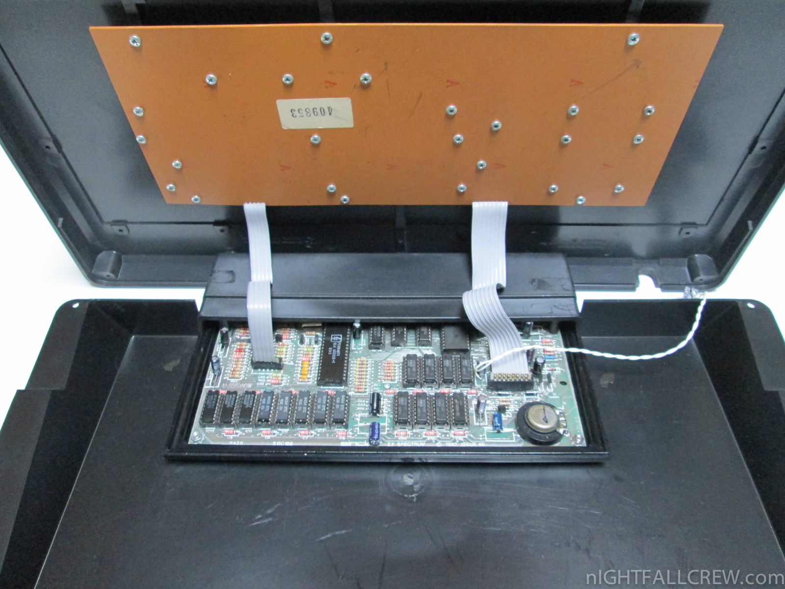
My usual sources do no longer sell a 74x245, but along these lines what about a CD4049? They are inverting, so it takes two. I would use them as buffers of the 5 keyboard-outputlines and 5 times 100k as pull up.
"Truth would quickly cease to be stranger than fiction, once we got used to it." - H.L. Mencken
-
1024MAK
- Bugaboo
- Posts: 3123
- Joined: Wed Nov 15, 2017 2:52 pm
- Location: Sunny Somerset in the U.K. in Europe
Re: Repairing a LO>>PROFILE professional keyboard
Other non-inverting buffer chips may work. The important things to consider are:
There is nothing stopping you from trying other chips though.
Mark
- The input threshold needs to be such that it will see a logic low/zero despite the voltage drop of the 1N4148 diodes on the Spectrum board and the Z80 address lines voltage may be only just be in tolerance for a logic low/zero,
- It can drive it’s outputs to very near to 0V,
- It is fast enough to switch each output on and off in sync with the Z80 address bus speeds
There is nothing stopping you from trying other chips though.
Mark
“There are four lights!”
Step up to red alert. Sir, are you absolutely sure? It does mean changing the bulb
Looking forward to summer later in the year.
Re: Repairing a LO>>PROFILE professional keyboard
Thanks for your thoughts. Off course 74HC or 74LS would be ideal for the reasons you listed, but at the moment I have to go with what I have.
But isn't this the True Sinclair way? Screw the specs, let's try something cheap and easy and hope it works!
Oh sorry, I forget to introduce you to someone very significant in my life.
Mark, this is my laziness.
My laziness ... Mark
Mark .. My laziness
Last edited by 1bvl109 on Tue Oct 22, 2019 7:53 pm, edited 1 time in total.
"Truth would quickly cease to be stranger than fiction, once we got used to it." - H.L. Mencken
-
1024MAK
- Bugaboo
- Posts: 3123
- Joined: Wed Nov 15, 2017 2:52 pm
- Location: Sunny Somerset in the U.K. in Europe
Re: Repairing a LO>>PROFILE professional keyboard
You do realise that you are chatting with someone who had a teacher who wrote “Mark can be lazy....” 
And someone who has bodged up all kinds of crazy stuff on stripboard and plenty of other experimental modifications to various items, including ZX Spectrums through to Atari STFMs
Mark
And someone who has bodged up all kinds of crazy stuff on stripboard and plenty of other experimental modifications to various items, including ZX Spectrums through to Atari STFMs
Mark
“There are four lights!”
Step up to red alert. Sir, are you absolutely sure? It does mean changing the bulb
Looking forward to summer later in the year.