Slauri wrote: ↑Sun Sep 22, 2019 5:31 pm
How do i check the voltages?
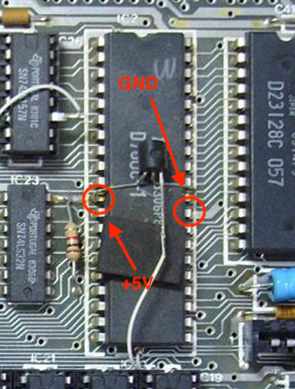
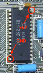
Set the multimeter in the DC voltage mode, select the 20V range, and touch the black (common) probe to the pin marked as GND in each picture and the red probe to the other pins as indicated. The indicated voltage values are nominal; your actual measurements might deviate slightly from them.
Lower RAM:
CPU:
ROM:
Every man should plant a tree, build a house, and write a ZX Spectrum game.
Please note that it is very important that you don’t accidentally short out any of the pins on the chips. So be careful with your meter probes.
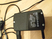
Can you post a photo of the power supply that you are using.
Mark
Standby alert
“There are four lights!”
Step up to red alert. Sir, are you absolutely sure? It does mean changing the bulb
Looking forward to summer later in the year.
Going on the rating plate/label, that power supply looks fine.
Mark
Standby alert
“There are four lights!”
Step up to red alert. Sir, are you absolutely sure? It does mean changing the bulb
Looking forward to summer later in the year.
Ast A. Moore wrote: ↑Sun Sep 22, 2019 2:50 pm
Wait, so you have an Issue 2 board in a Spectrum+ case?
I have an issue 2 Spectrum+, it's an Upgrade case.
Sure, I know they existed. It’s just they don’t pop up all that often; so, whenever I see someone mention a Spectrum+, I assume it’s an Issue 4A or later.
Every man should plant a tree, build a house, and write a ZX Spectrum game.
Hi,
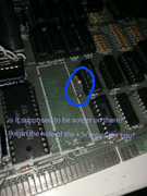
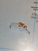
I have now removed the old cpu from the pcb. I don't remember, that is the resistor on the left side of the cpu supposed to be connected to the +5v leg of the cpu. I'll put a picture here so you can get better understanding of what i mean. I just want to be sure.
Standby alert
“There are four lights!”
Step up to red alert. Sir, are you absolutely sure? It does mean changing the bulb
Looking forward to summer later in the year.
ZX Spectrum Issue 1 and 2 boards
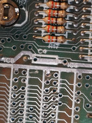
Extra resistor near the CPU.
This is R73, a 1kΩ resistor connected between +5V and ULA pin 32 / R24 / C67 (D14).
From the service manual:
service manual wrote:This modification is required for efficient operation of certain machine code software and should be implemented on all units. It has been implemented in manufacture for all ULAs 5C112-2 and later.
D14 replaced by C67 (100pF)
R24 changed from 3k3 to 1k
R27 changed from 680R to 470R
R73 (1k) added between IC1/32 and +5V
Mark
Standby alert
“There are four lights!”
Step up to red alert. Sir, are you absolutely sure? It does mean changing the bulb
Looking forward to summer later in the year.
I picked up some 100nF (I think) capacitors like that from a surplus supplier (Greenweld) many years ago.
Anyhoo, the machine should still work with it missing. I do however recommend you fit a modern 47nF or 100nF multilayer ceramic as a replacement.
Mark
Standby alert
“There are four lights!”
Step up to red alert. Sir, are you absolutely sure? It does mean changing the bulb
Looking forward to summer later in the year.
And it doesn’t hurt to combine several capacitors of different values in parallel, say a 47nF and a 1µF one. Each capacitor will operate at a different frequency, because their efficiency is very frequency dependent. In some cases, however, it’s mostly gilding the lily.
Every man should plant a tree, build a house, and write a ZX Spectrum game.