Two faulty 4A Spectrums

For experts to discuss very technical stuff and newbies to ask why the Spectrum they bought off ebay doesn't work.
Post Reply
ejej
Drutt
Posts: 3
Joined: Sun Nov 03, 2019 10:29 pm

Two faulty 4A Spectrums

Post by ejej »

Hi everyone. I've recently got two Spectrums - they're my first ones, so I'm completely new to the topic. As the title says, they unfortunately don't work. Here are the symptoms:

1) Spectrum Plus

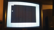
When I first plugged it in, it didn't react to anything. I checked the voltages in it and found that the voltage regulator was outputting 8,33V instead of 5. The ULA would also get very hot, so much so that I practically couldn't touch it. I replaced the regulator and also recapped the board. I've arrived at this:

Image

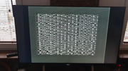
The pattern constantly changes, it almost seems as if it was rolling from top to bottom.

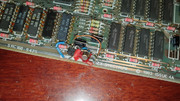
I've also noticed a few irregularities on the board itself. From my research it seems that someone tried doing the DC-DC conversion described in this Spectrum service manual I found (page 48) - https://spectrumforeveryone.com/wp-cont ... Manual.pdf. It also seems to me that this modification wasn't completed - here are the pictures of what was done. Before I figured out that this isn't how the standard board looks, I've replaced both capacitors used in the modification and also put C47 back onto the board.

ImageImage
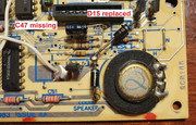
Ignore the rather poorly installed C50, it was a placeholder ;)

The manual states that this modification doesn't change how the circuit works, so I guess I shouldn't worry about it?

2) classic Spectrum

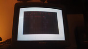
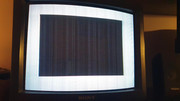
The previous owner claimed to have used it about a year ago and that it was fine then. When I plug it in, the board itself makes a high-pitched, kind of gritty noise - I assume this to be a faulty coil, but I haven't replaced it. The voltages all seem to be present and fine, but the computer boots with graphical glitches. These vary a lot. Often it's just a black paper area, sometimes with some artefacts on it. Sometimes it displays a black screen and seems to be rebooting constantly - the noise it makes changes in pitch and the artefacts on screen change. A few times the speaker made a singular pop when this was going on. It has actually booted up correctly a few times, but the picture was oddly fuzzy and it also wasn't reacting to inputs, but that might've been the keyboard since both of them have ripped cables - I must get to fixing that. I recapped this board as well. Here are a few pictures I took:

ImageImageImageImageImage

I've also recorded a video of what it does, which includes the most extraordinary glitch it produced (the first one in the video) - https://drive.google.com/open?id=12OkZr ... sWKsbv302L

The changes in the high-pitched noise are audible towards the end of the video, but they're very hard to make out sadly.

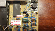
The board in this one also seems to have a modification on it, although I've no clue what it's supposed to do.

ImageImage

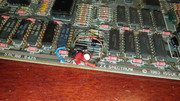
ICs 6 through 11 as well as the Z80 seem to have been replaced in the past, judging by the soldering.

I have also tried something rather risky - I swapped the ULAs between the two, but the behaviour didn't change. I hope that this means that both ULAs are fine...

From what I've read, this most likely is a memory issue. I'm kind of at my wit's end as to what to do now. How would I go about checking the memory?

All responses are greatly appreciated :)
User avatar
1024MAK
Bugaboo
Posts: 3115
Joined: Wed Nov 15, 2017 2:52 pm
Location: Sunny Somerset in the U.K. in Europe

Re: Two faulty 4A Spectrums

Post by 1024MAK »

The first Spectrum 4A board that you talk about... (the ZX Spectrum+)...

Before doing anything else, what voltages do you now get on the -5V supply and the +12V supply?
Test on the pins on one of the 4116 (or equivalent) DRAM chips (IC6 ... IC13)
Pin 1, VBB, -5V
Pin 8, CDD, +12V

Or on the edge connector.

Also please test the +12VA on pins 14, 15 & 16 (they should all be linked together) on IC14 (LM1889).

About the DC/DC converter: some 4A boards were modified during or after construction. Some boards were modified if they were sent back to Sinclair for service / repair. Some independent service / repair shops also would upgrade the board with this modification.

I posted the correct modification details here. This DC/DC modification improves the design of the DC/DC converter. So I strongly suggest you examine your board and bring it up to the design I posted here.

The photo you posted indicates a problem with a very low +12VA and a problem with the ‘lower RAM’ comprised of the eight 4116 (or equivalent) DRAM chips. Both of these may be caused by missing -5V and +12V supplies.

—————————————————————————————————————————————————————————————————————————

The second issue 4A Spectrum board, the classic or rubber key...

The coil often makes a high pitched whine in older issue boards. Sinclair are supposed to have reduced the noise from later issue boards. All that is happening is that it is vibrating at the switching frequency. Use some nail varnish or PCB varnish/conformal coating to cover the windings. Don’t overdo this in case you need to remove it from the board...

Yes, this board looks like it has a RAM problem. It does not look like it is the ‘lower’ 4116 DRAM chips that are the cause, but the ‘upper’ 32K bit DRAM chips (IC15 ... IC22).

The Z80 CPU is able to run the code from the ROM, but is often getting stuck during the memory check.

To disable the "upper" 32k of RAM, (so attempt to eliminate this as the problem) take a piece of wire and connect pin 5 on IC23 (a 74LS32) to +5V. (link).

I suggest you make a temporary solder connection with an SPST on/off switch in series. Start with the switch set to on. Then if you get to the copyright screen and BASIC works, after that, you can turn the switch off so that some simple BASIC commands can access and therefore test the upper RAM.

This is done because the ROM code tries to see how much RAM there is at start-up. After this, the BASIC ROM will ignore any RAM that is not present (or in this case, is disabled)(well, unless you reset the limits using CLEAR n). But the BASIC POKE and PEEK commands have no limits and work across the whole Z80 address range.

Double and triple check that you have the correct pin on the correct chip, or you WILL damage something. This temporary modification will disable the "upper" RAM (when the switch is ON), as the CAS control signal won't reach the RAM chips.

Note that if a faulty DRAM IC is jamming one of the data lines, this won't really help.

I have never seen the modification that you have on this board before. For now I suggest you leave it alone.
But I would like you to take some more photos of it. From directly over the top, from the left hand side of the board, the right hand side, and from the edge-connector side.

You may want to check the DC/DC converter circuitry with the details I linked to earlier.

I recommend these replacement keyboard membranes: rubber key, plus keyboard.

Mark
:!: Standby alert :!:
“There are four lights!”
Step up to red alert. Sir, are you absolutely sure? It does mean changing the bulb :dance
Looking forward to summer later in the year.
User avatar
Ast A. Moore
Rick Dangerous
Posts: 2641
Joined: Mon Nov 13, 2017 3:16 pm

Re: Two faulty 4A Spectrums

Post by Ast A. Moore »

1024MAK wrote: Mon Nov 04, 2019 12:30 pm The Z80 CPU is able to run the code from the ROM, but is often getting stuck during the memory check.
The pictures do suggest that. However, the video starts with what looks like a blue border. Could be the artifact of the camera’s white balance/exposure, though.
Every man should plant a tree, build a house, and write a ZX Spectrum game.

Author of A Yankee in Iraq, a 50 fps shoot-’em-up—the first game to utilize the floating bus on the +2A/+3,
and zasm Z80 Assembler syntax highlighter.
ejej
Drutt
Posts: 3
Joined: Sun Nov 03, 2019 10:29 pm

Re: Two faulty 4A Spectrums

Post by ejej »

Thank you so much for the detailed response, I will get to doing all of that soon and will report what I got.

As for the video, the border in the beginning of it was blue, it was not the camera acting funny.
User avatar
1024MAK
Bugaboo
Posts: 3115
Joined: Wed Nov 15, 2017 2:52 pm
Location: Sunny Somerset in the U.K. in Europe

Re: Two faulty 4A Spectrums

Post by 1024MAK »

ejej wrote: Tue Nov 05, 2019 3:00 am Thank you so much for the detailed response, I will get to doing all of that soon and will report what I got.

As for the video, the border in the beginning of it was blue, it was not the camera acting funny.
That’s strange :shock:

Mark
:!: Standby alert :!:
“There are four lights!”
Step up to red alert. Sir, are you absolutely sure? It does mean changing the bulb :dance
Looking forward to summer later in the year.
User avatar
Ast A. Moore
Rick Dangerous
Posts: 2641
Joined: Mon Nov 13, 2017 3:16 pm

Re: Two faulty 4A Spectrums

Post by Ast A. Moore »

1024MAK wrote: Tue Nov 05, 2019 3:19 pm
ejej wrote: Tue Nov 05, 2019 3:00 am Thank you so much for the detailed response, I will get to doing all of that soon and will report what I got.

As for the video, the border in the beginning of it was blue, it was not the camera acting funny.
That’s strange :shock:
Yup. Don’t like it one bit.

Wouldn’t hurt to swap the CPU for a known good one.
Every man should plant a tree, build a house, and write a ZX Spectrum game.

Author of A Yankee in Iraq, a 50 fps shoot-’em-up—the first game to utilize the floating bus on the +2A/+3,
and zasm Z80 Assembler syntax highlighter.
ejej
Drutt
Posts: 3
Joined: Sun Nov 03, 2019 10:29 pm

Re: Two faulty 4A Spectrums

Post by ejej »

I chcecked the voltages in the Spectrum +, both -5V and 12V are missing. I also checked the DC-DC modification and it seems to be in order. I read that 12V is produced by the TR4 transistor, so I checked the voltage on the base pin of it. It showed slightly above 10V, so I assumed it was faulty and went ahead with replacing it, using a ZTX653. I plugged the Spectrum in and as I was reaching for my multimeter, the transistor started smoking quite badly. I immediately unplugged it. Any thoughts as to what could've caused that?
User avatar
1024MAK
Bugaboo
Posts: 3115
Joined: Wed Nov 15, 2017 2:52 pm
Location: Sunny Somerset in the U.K. in Europe

Re: Two faulty 4A Spectrums

Post by 1024MAK »

Most likely, one or more of the 4116 (or equivalent) DRAM chips have gone faulty. Either this caused the failure of the original TR4 transistor, or miss-use of the edge-connector (short circuit) killed the transistor, and then, the lack of the -5V supply resulted in one or more of the 4116 DRAM chips self destructing. When a 4116 dies, it often draws excessive current from the 12V rail, overloading TR4. In any event, a new transistor will need fitting.

It is also possible that when the original TR4 died, so did TR5. Either remove and test TR5 (if you have a suitable tester), or better still, renew it. Any reasonable quality PNP small signal transistor should work, just watch the lead-out, as very few have the same lead out and case outline as the ZTX213 (which is obsolete).

There are a number of ways to proceed. Options include:
  • Leave out TR4, and (assuming the DC/DC converter circuit has capacitor C78 / C80 fitted), use an external regulated bench PSU with +12V and -5V outputs to temporarily supply the board. This PSU must have adjustable current limited outputs.
  • Cut a PCB track, or lift component legs so as to isolate the +12V rail from ALL the 4116 DRAM chips, replace TR4 (check or replace TR5), power up and test the +12V and -5V from the DC/DC converter,
  • Cut pin 8 on each 4116 DRAM chip, to isolate each one. Cut in such a way, that you can join the leg together with some solder if the chip tests okay / or for testing one chip at a time. Power up while holding your finger on TR4 with the other hand ready to pull the power... Also if no problems with TR4 overheating, test the +12V and the -5V.
  • Desolder / cut out ALL of the existing 4116 DRAM chips, then test all the PCB tracks and the plated through holes, fit sockets, then either fit replacement DRAM chips, or try the removed DRAM chips one at a time while holding your finger on TR4 with the other hand ready to pull the power... (as above). If desoldering, be VERY careful, as it is far too easy to damage the PCB tracks, pads or the plated through holes.
There are some resistance tests that may indicate the faulty chip, read this fault finding guide. Note that the author is correct in that TR4 must be a ZTX650, ZTX651 or ZTX653, but incorrect with regards to TR5, which does NOT have to be a ZTX213.

It is also possible that “the coil” has been overloaded and over heated in the past, causing shorts between the windings.

Have a think, and please ask if you need more information, help or advice.

Mark
:!: Standby alert :!:
“There are four lights!”
Step up to red alert. Sir, are you absolutely sure? It does mean changing the bulb :dance
Looking forward to summer later in the year.
Post Reply