Page 1 of 1
Help repairing my ZX Spectrum+
Posted: Sun Nov 10, 2019 7:44 pm
by Olipix
Hi guys
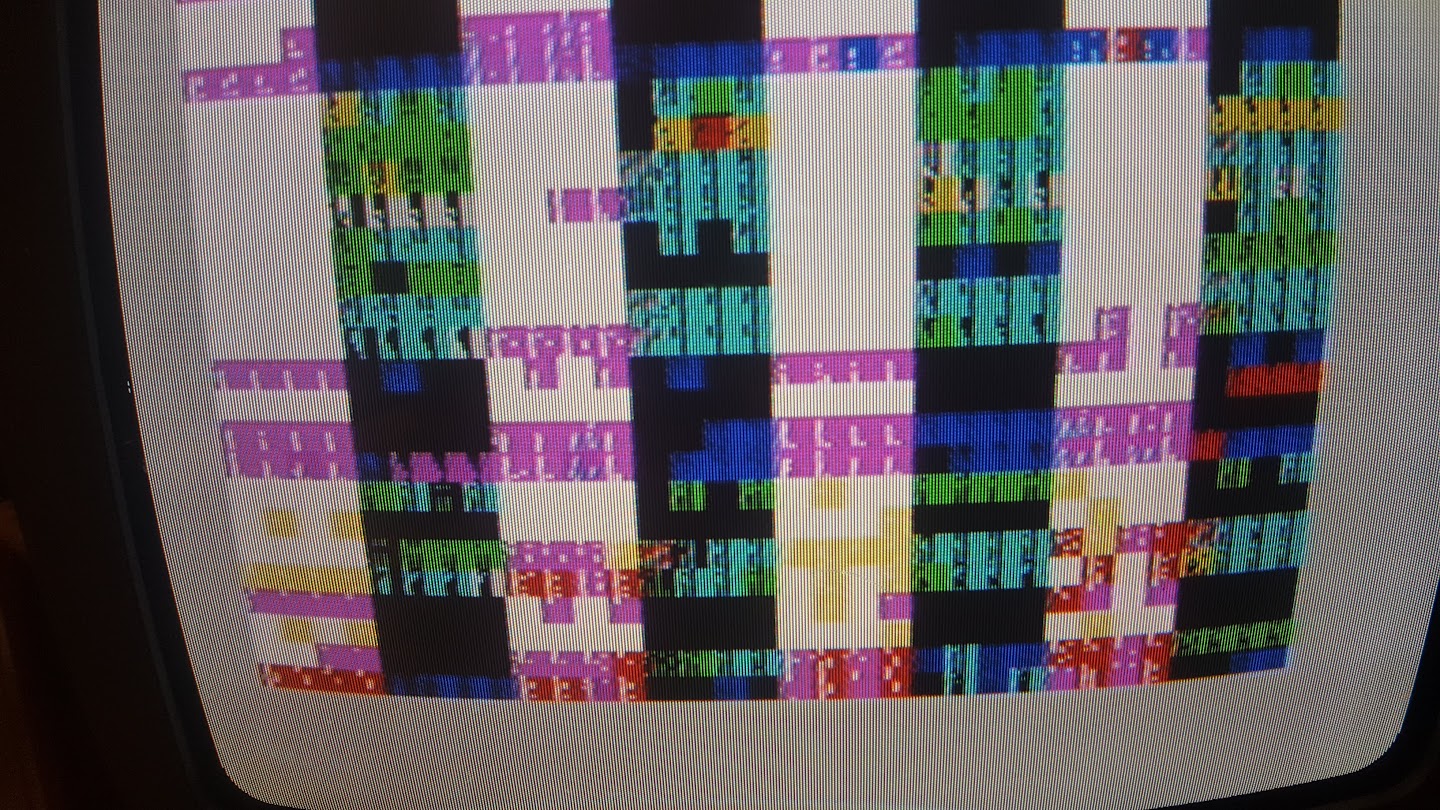
Can someone help me identifying the problem my ZX Spectrum+ has ?
The motherboard is an issue 4B
This is the actual display right now :
So far here is what I've done on this speccy :
Capcitors C34, C50, C44, and C45 changed
Transistor TR4 changed
Voltage regulator changed
All the 4116 RAMs have been tested and are ok.
+5, -5 and 12v voltages are ok
Could you help me identifying what may be wrong ?
ULA ? Z80 ? ROM ?
This type of garbaged display might be symptomatic of a specific problem?
Thanks for any help
Re: Help repairing my ZX Spectrum+
Posted: Sun Nov 10, 2019 8:19 pm
by 1024MAK
Does the border always turn to white when you power down, then up?
If yes, that’s a good indication that the Z80 CPU is able to read the first part of the ROM okay.
What happens when you press the reset switch/button?
Can you record a video of it as you power it up, or reset it please (upload to YouTube or somewhere else that lets you upload videos.
Is this a 48K model (although the ZX Spectrum+ was only available as a 48K version, ZX Spectrum+ cases & keyboards were available for users to upgrade their rubber key models) ?
And can you please report back which, if any chips are in sockets.
Also, can you please tell us how the 4116 DRAM chips were tested.
Mark
Re: Help repairing my ZX Spectrum+
Posted: Mon Nov 11, 2019 8:43 am
by Olipix
Thanks Mark for your quick reply !
> Does the border always turn to white when you power down, then up?
yes
> What happens when you press the reset switch/button?
Well, the reset wires are desoldered and I don't know where exactly to resolder them.
Can you help with that ?
I will record a video when the reset button will be reinstalled
> Is this a 48K model
Yes
This is the mother board :

> And can you please report back which, if any chips are in sockets.
The ULA and the low RAM 4116s are on socket
> Also, can you please tell us how the 4116 DRAM chips were tested.
I have tested all the RAMs on a working Colecovision.
1 RAM chip was broken, and I have replaced it with a "new old stock" working one.
Re: Help repairing my ZX Spectrum+
Posted: Mon Nov 11, 2019 9:45 am
by Ast A. Moore
Olipix wrote: ↑Mon Nov 11, 2019 8:43 am
Well, the reset wires are desoldered and I don't know where exactly to resolder them.
On a Spectrum+, they are typically soldered directly to the leads of C27, which sits across the
RESET and GND pins of the CPU.
Re: Help repairing my ZX Spectrum+
Posted: Mon Nov 11, 2019 9:48 am
by Olipix
Yes, I found the information too this morning...
I soldered the reset button on both sides of the C27, bit it seems to do nothing on the computer when I press the reset button...
Here is the video :
https://www.youtube.com/watch?v=ai-S3MqJbuU
I noticed that if I let the computer powered on for a few minutes, borders start to change colour from white to blue or red, then black...
Re: Help repairing my ZX Spectrum+
Posted: Mon Nov 11, 2019 10:35 am
by Ast A. Moore
Thanks for making the video.
Olipix wrote: ↑Mon Nov 11, 2019 9:48 am
I noticed that if I let the computer powered on for a few minutes, borders start to change colour from white to blue or red, then black...
This is curious. Wait until the border changes to something other than white, then press the reset button momentarily. Does the border become white?
If it does, than it looks like the CPU can execute a few ROM instructions, including a jump. I’d check the address lines for continuity/shorts. Possibly a broken trace or a solder splash.
Re: Help repairing my ZX Spectrum+
Posted: Mon Nov 11, 2019 11:35 am
by Olipix
I've made a second video :
https://youtu.be/nYZ58mBKXqw
After a few minutes (at first Reset does nothing), pressing the reset button change the border color !!
Does that help to narrow the problem ?
Do you have a guideline to test the address lines for continuity ?
Thanks for your help
Re: Help repairing my ZX Spectrum+
Posted: Mon Nov 11, 2019 11:58 am
by Ast A. Moore
Olipix wrote: ↑Mon Nov 11, 2019 11:35 am
After a few minutes (at first Reset does nothing), pressing the reset button change the border color !!
Yes, but not to white.
Olipix wrote: ↑Mon Nov 11, 2019 11:35 amDoes that help to narrow the problem ?
I’m kind of suspecting the CPU/ROM now. At this point, I’d replace them with known good parts beginning with the CPU. If you have an oscilloscope, check the clock at Pin 6 of the CPU.
Olipix wrote: ↑Mon Nov 11, 2019 11:35 amDo you have a guideline to test the address lines for continuity ?
Nothing specific other than using a multimeter in continuity mode with the computer unplugged from the power source. Test each address line for continuity from the CPU to ROM, RAM, and multiplexor ICs (IC3, IC4, and IC 24). Test each address line for shorts with each other at a few points (CPU/ROM).
Re: Help repairing my ZX Spectrum+
Posted: Mon Nov 11, 2019 2:38 pm
by Olipix
Sadly, I don't have any Oscilloscope right now
I will change the Z80 first and let you know what happens
Thanks guys for your help
Re: Help repairing my ZX Spectrum+
Posted: Mon Nov 11, 2019 6:18 pm
by 1024MAK
Ast A. Moore wrote: ↑Mon Nov 11, 2019 9:45 am
Olipix wrote: ↑Mon Nov 11, 2019 8:43 am
Well, the reset wires are desoldered and I don't know where exactly to resolder them.
On a Spectrum+, they are typically soldered directly to the leads of C27, which sits across the
RESET and GND pins of the CPU.
See this photo:

Before trying to change any soldered in chips, do you have experience of desoldering?
Mark
Re: Help repairing my ZX Spectrum+
Posted: Tue Nov 12, 2019 9:05 am
by Olipix
I have a little experience.
I have already desoldered some chips, smaller than the Z80, with success without damaging the board.
I know it's complicated but I have to do it

I think I will have to cut the Z80 legs first, otherwise it will be very tricky.
Do you have suggestions or advices ?
Regards
Re: Help repairing my ZX Spectrum+
Posted: Tue Nov 12, 2019 11:31 am
by Ast A. Moore
Olipix wrote: ↑Tue Nov 12, 2019 9:05 am
I think I will have to cut the Z80 legs first, otherwise it will be very tricky.
Do you have suggestions or advices ?
That seems a bit drastic given that we don’t know if the CPU is dead for sure, but I can understand your apprehension. With care, it is possible to desolder it without cutting the leads, but if you don’t feel confident enough, it’s best to sacrifice the CPU rather than the PCB.
A hand-held solder sucker and desoldering braid can go a long way. Apply a little bit of fresh solder to the joint and then, while still heating it with the iron, quickly press the nozzle of the solder sucker to the joint, remove the iron tip, and release the spring-loaded piston at the same time. This all must be done in one swift and decisive motion. The nozzle of the solder sucker must be pressed to the joint firmly enough to ensure a good seal.
Re: Help repairing my ZX Spectrum+
Posted: Fri Dec 06, 2019 4:43 pm
by Olipix
Hello guys
I've changed the Z80 (I even managed to preserve the original one) and I've changed the ULA and...
the problem is still the same : multi colored artefacts at boot + border that change color when Reset is pressed....
Any recommandations ?
Should I change the ROM too ?
Thanks for any advice
Re: Help repairing my ZX Spectrum+
Posted: Fri Dec 06, 2019 5:24 pm
by Ast A. Moore
Yes, replacing the ROM is a logical next step. If that doesn’t help, I’d really start looking into shorts/broken traces.
Re: Help repairing my ZX Spectrum+
Posted: Sat Dec 07, 2019 12:32 am
by 1024MAK
Before desoldering the ROM, it’s possible to disable it (if it’s not completely dead).
On the edge connector, pin 25 on the underside can be connected to +5V to tell the ROM to ignore any reads. Alternatively you can connect to the appropriate lead of resistor R33 (680Ω). Make sure you connect to the lead that goes to edge connector pin 25.
In this state the ROM chip should turn off its output pins. Now the Z80 will read whatever value the data bus floats to. Which, if there are no misbehaving chips fitted, should be 255 (FFh or 0xFF) due to ‘pull-up’ resistors R9 to R16.
As far as the Z80 is concerned 0xFF means RST 38h. When the Z80 executes this instruction, the current PC value plus one is pushed onto the stack, then the PC is loaded with 38h (0x38). The Z80 then fetches the instruction at this address which is again 0xFF.
The end result is that all RAM will fill up with the values that are being pushed to the stack, as the stack pointer works its way through all possible addresses before wrapping around and then doing it all again.
If the screen RAM and the ULA are working, this will produce a distinctive diagonal pattern on the screen.
Mark
Re: Help repairing my ZX Spectrum+
Posted: Sat Dec 07, 2019 2:36 pm
by Olipix
Excellent.
So, to test this I only have to solder a wire between pin 25 and +5v ?
Re: Help repairing my ZX Spectrum+
Posted: Sat Dec 07, 2019 3:22 pm
by 1024MAK
Olipix wrote: ↑Sat Dec 07, 2019 2:36 pm
Excellent.
So, to test this I only have to solder a wire between pin 25 and +5v ?
No, don’t solder to the edge-connector

If you have a spare female edge-connector socket, or a simple interface like a joystick interface, use either a test clip or solder to the relevant pins on the edge-connector socket.
If you don’t have anything suitable, use the resistor. First, with the power off and disconnected, switch your multimeter to the 200 ohm resistance range (or equivalent). Now test between each lead of resistor R33 and pin 25 on the underside (of the board) of the edge-connector contacts. When your meter shows a resistance of less than 1 ohm, you now know you have the correct lead of resistor R33. You can now either attach a test clip and then connect to any +5V point. Or you can solder a wire to the same resistor lead or the solder connection on the underside of the board.
Please do double check your work before powering on. Making a mistake and applying +5V to the wrong place would not be a good thing to do...
Mark
Re: Help repairing my ZX Spectrum+
Posted: Sun Dec 08, 2019 11:28 am
by Olipix
Ok, I've linked the right leg of the R33 and +5v, and this is what it gives :
https://youtu.be/lPLKieSuBcc
Any thoughts ?
Re: Help repairing my ZX Spectrum+
Posted: Sun Dec 08, 2019 7:04 pm
by 1024MAK
Yeah, there is no sign of the Z80 writing to screen memory

I understand you have a multimeter. But don’t have or have access to an oscilloscope.
Do you have a logic probe or a logic analyser?
Mark
Re: Help repairing my ZX Spectrum+
Posted: Mon Dec 09, 2019 8:12 am
by Olipix
Thanks Mark for the reply
Indeed I have nos oscilloscope right now
But I have this, if it can help...

Re: Help repairing my ZX Spectrum+
Posted: Mon Dec 09, 2019 10:35 am
by 1024MAK
I can’t see the picture that you tried to post. Can you use the “Add image to post” function (just below the text edit box) to include pictures please.
Mark
Re: Help repairing my ZX Spectrum+
Posted: Mon Dec 09, 2019 11:24 am
by Olipix
Sorry. I did as you said, but the URL was in fact private.
here is the pciture of the tool I have :

Re: Help repairing my ZX Spectrum+
Posted: Sun Jan 12, 2020 2:58 pm
by Olipix
Hi guys !
Just to let you know that I managed to get my ZX Spectrum+ working.
It was the Z80 !
Thanks for all your help
Now I'm onto trying to save another Spectrum+...
Re: Help repairing my ZX Spectrum+
Posted: Sun Jan 12, 2020 5:55 pm
by Ast A. Moore
Glad we could help!