Stuck with repair of Spectrum+
-
Firefox
Re: Stuck with repair of Spectrum+
I can't quite tell reading the thread back - did you eventually replace IC12 (lower RAM IC), or is it still missing?
-
1024MAK

- Bugaboo
- Posts: 3118
- Joined: Wed Nov 15, 2017 2:52 pm
- Location: Sunny Somerset in the U.K. in Europe
Re: Stuck with repair of Spectrum+
Before desoldering the ROM, it’s possible to disable it (if it’s not completely dead).
On the edge connector, pin 25 on the underside can be connected to +5V to tell the ROM to ignore any reads. Alternatively you can connect to the appropriate lead of resistor R33 (680Ω).
In this state it should turn off its output pins. Now the Z80 will read whatever value the data bus floats to. Which, if there are no misbehaving chips fitted, should be 255 (FFh or 0xFF) due to ‘pull-up’ resistors R9 to R16.
As far as the Z80 is concerned 0xFF means RST 38h. When the Z80 executes this instruction, the current PC value plus one is pushed onto the stack, then the PC is loaded with 38h. The Z80 then fetches the instruction at this address which is again 0xFF.
The end result is that all RAM will fill up with the values that are being pushed to the stack, as the stack pointer works its way through all possible addresses before wrapping around and then doing all again.
If the screen RAM and the ULA are working, this will produce a distinctive diagonal pattern on the screen.
Mark
“There are four lights!”
Step up to red alert. Sir, are you absolutely sure? It does mean changing the bulb
Looking forward to summer later in the year.
-
1024MAK
- Bugaboo
- Posts: 3118
- Joined: Wed Nov 15, 2017 2:52 pm
- Location: Sunny Somerset in the U.K. in Europe
Re: Stuck with repair of Spectrum+
Yes, the soldering does not look very professionalspeccyplus wrote: ↑Mon Apr 20, 2020 7:46 pm One of the upper ram chips looks pretty crunchy. May pull those, as I plan to just socket all the ram anyways.
The CPU has also been socketed by someone.
It is worthwhile cleaning the brown flux odd the board and visually inspecting it. You are looking for possible solder splashes, broken or cracked tracks and dry solder joints. If I’m telling granny to suck eggs, forgive me. It’s hard to tell how much experience you have.
Mark
“There are four lights!”
Step up to red alert. Sir, are you absolutely sure? It does mean changing the bulb
Looking forward to summer later in the year.
-
1024MAK
- Bugaboo
- Posts: 3118
- Joined: Wed Nov 15, 2017 2:52 pm
- Location: Sunny Somerset in the U.K. in Europe
Re: Stuck with repair of Spectrum+
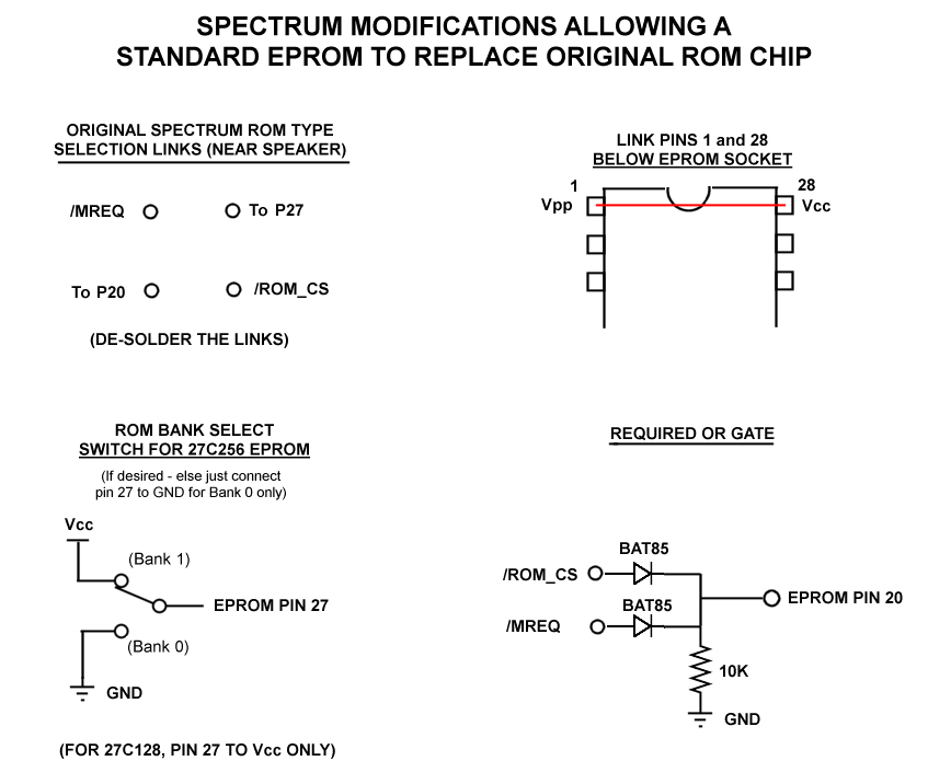
You can replace the ROM chip with a 27128, 27C128, 27256 or 27C256. However you will need to add a wired OR gate as per the details here. The reason being is that a EPROM only has a single chip select input, but the ROM has two chip select inputs.
You can download the “48.rom” file from this site.
If you you use a 27256 or 26C256, you can put this diagnostic ROM into the top half of the EPROM. Then wire a small switch to the highest address line (pin 27) to select between the normal ROM and the diagnostic ROM
The diagnostic ROM does not need any working RAM to run basic tests. So as long as the CPU is running and the ULA is working, it can be a valuable test tool.
Mark
“There are four lights!”
Step up to red alert. Sir, are you absolutely sure? It does mean changing the bulb
Looking forward to summer later in the year.
-
speccyplus
- Drutt
- Posts: 46
- Joined: Wed Apr 15, 2020 5:41 pm
Re: Stuck with repair of Spectrum+
I replaced it with a modified 4164, that was known good. I am waiting on replacement 4116s. Whenever I do tests, I do it with and without the that ram chip.
-
speccyplus
- Drutt
- Posts: 46
- Joined: Wed Apr 15, 2020 5:41 pm
Re: Stuck with repair of Spectrum+
I'm just a hobbyist, but yeah have been looking for that stuff. I am getting free help and experience, so any advice is good in my book! I just cleaned the board, and attempted to remove that crusty chip, but as luck would have it there was some corrosion/gunk on the component side, and it started to lift 2 traces. So I pushed the chip back in and put in fresh solder and checked continuity from the pins down the trace. Still works, will save that one for when I am ready to do bodge wire repairs.1024MAK wrote: ↑Mon Apr 20, 2020 10:27 pmYes, the soldering does not look very professionalspeccyplus wrote: ↑Mon Apr 20, 2020 7:46 pm One of the upper ram chips looks pretty crunchy. May pull those, as I plan to just socket all the ram anyways.
The CPU has also been socketed by someone.
It is worthwhile cleaning the brown flux odd the board and visually inspecting it. You are looking for possible solder splashes, broken or cracked tracks and dry solder joints. If I’m telling granny to suck eggs, forgive me. It’s hard to tell how much experience you have.
Mark
-
speccyplus
- Drutt
- Posts: 46
- Joined: Wed Apr 15, 2020 5:41 pm
Re: Stuck with repair of Spectrum+
Just did this test, here are the results:1024MAK wrote: ↑Mon Apr 20, 2020 8:39 pm Before desoldering the ROM, it’s possible to disable it (if it’s not completely dead).
On the edge connector, pin 25 on the underside can be connected to +5V to tell the ROM to ignore any reads. Alternatively you can connect to the appropriate lead of resistor R33 (680Ω).
In this state it should turn off its output pins. Now the Z80 will read whatever value the data bus floats to. Which, if there are no misbehaving chips fitted, should be 255 (FFh or 0xFF) due to ‘pull-up’ resistors R9 to R16.
As far as the Z80 is concerned 0xFF means RST 38h. When the Z80 executes this instruction, the current PC value plus one is pushed onto the stack, then the PC is loaded with 38h. The Z80 then fetches the instruction at this address which is again 0xFF.
The end result is that all RAM will fill up with the values that are being pushed to the stack, as the stack pointer works its way through all possible addresses before wrapping around and then doing all again.
If the screen RAM and the ULA are working, this will produce a distinctive diagonal pattern on the screen.
Mark
-
1024MAK
- Bugaboo
- Posts: 3118
- Joined: Wed Nov 15, 2017 2:52 pm
- Location: Sunny Somerset in the U.K. in Europe
Re: Stuck with repair of Spectrum+
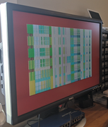
Not good.
Something similar to this image is what is supposed to happen:
So clearly something else is going wrong. I suspect either the Z80 is faulty, one or more address, control or data lines are open circuit (or possibly shorted to something else), or IC3 and/or IC4 is faulty (both 74LS157).
Schematic here.
Mark
“There are four lights!”
Step up to red alert. Sir, are you absolutely sure? It does mean changing the bulb
Looking forward to summer later in the year.
-
speccyplus
- Drutt
- Posts: 46
- Joined: Wed Apr 15, 2020 5:41 pm
Re: Stuck with repair of Spectrum+
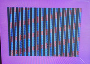
I just ordered a z80, will try that next, will source a couple 74LS157 as well.
I can also start checking for continuity from the cpu socket to other spots on the board, make sure they are zero ohms. I have nothing that is open on the socket, everything I think can reach ground except the M1 line and a few lines that go to the edge connectors, I recall 3 maybe?
I can also start checking for continuity from the cpu socket to other spots on the board, make sure they are zero ohms. I have nothing that is open on the socket, everything I think can reach ground except the M1 line and a few lines that go to the edge connectors, I recall 3 maybe?
-
1024MAK
- Bugaboo
- Posts: 3118
- Joined: Wed Nov 15, 2017 2:52 pm
- Location: Sunny Somerset in the U.K. in Europe
Re: Stuck with repair of Spectrum+
Any lines that only go the the edge-connector, such as /M1, don’t need to be continuity tested. But still do need testing to see if they have a short between them and anything else. When testing for short circuits, concentrate initially on testing each line to the 0V and to the +5V supply rails. Then to any signal line that may have a track that runs next to, or near to the line under investigation.
Obviously some lines (control inputs such as /NMI) are tied to the +5V rail via resistors.
The data bus, and the 4116 DRAM address bus are both provided with series resistors that act as crude bus isolators.
When working to the published schematics, keep in mind that the actual track layout and connections were done for ease of routing. So for DRAM for example, they may have swapped around some address or data lines. The same applies to the inputs / gates on the 74LSxxx series logic chips.
Which Z80 did you buy?
Any rated at 4MHz or a faster speed should work. The original fitted chip would have been a Z80A or equivalent. CMOS Z80s do work as well and are available brand new from the larger electronic companies (e.g. RS components).
Mark
“There are four lights!”
Step up to red alert. Sir, are you absolutely sure? It does mean changing the bulb
Looking forward to summer later in the year.
-
speccyplus
- Drutt
- Posts: 46
- Joined: Wed Apr 15, 2020 5:41 pm
Re: Stuck with repair of Spectrum+
Got this one, slightly faster at 6mhz than the 4mhz one in there now.
-
speccyplus
- Drutt
- Posts: 46
- Joined: Wed Apr 15, 2020 5:41 pm
Re: Stuck with repair of Spectrum+
So I pulled IC3 and IC4, they are 74HC257s. Not 157s like the diagram you posted, I hate that all the pins are not clipped, but folded over, pain to solder suck, have to bend them and risk damage to the pads on the bottom. Second one took forever to pull so I would not damage the board.
I don't think the LS257 I had would work, since HC I think float high and and the LS use more power.
Anyways pulled them both, they tested OK. However pins are so mangled and would not fit in the sockets clean, ordered some exact replacements.
Gonna pull the other ones and test as well when I have time again.
Anyways same results putting back in so means my socket work is good!
Spent some more time scouring the board, I see nothing bridged on the bottom, except 3 pins that look like they are soldered together on the IC 14 chip, pins 13,14 and 15 I believe, on the bottom. This was the replaced chip by previous owner.
I don't want to pull the CPU socket, as I am worried the crappy previous soldering job may cause damage.
For giggles I ran without each of the 74HC257s to see the screen change, and yes, it looks similar in behavior but different.
-
Firefox
Re: Stuck with repair of Spectrum+
Pins 14, 15 and 16 should be shorted together...speccyplus wrote: ↑Wed Apr 22, 2020 1:50 am Spent some more time scouring the board, I see nothing bridged on the bottom, except 3 pins that look like they are soldered together on the IC 14 chip, pins 13,14 and 15 I believe, on the bottom. This was the replaced chip by previous owner.
(edit) That looks correct in your photo of the PCB underside.
-
speccyplus
- Drutt
- Posts: 46
- Joined: Wed Apr 15, 2020 5:41 pm
Re: Stuck with repair of Spectrum+
Thanks!Firefox wrote: ↑Wed Apr 22, 2020 1:04 pmPins 14, 15 and 16 should be shorted together...speccyplus wrote: ↑Wed Apr 22, 2020 1:50 am Spent some more time scouring the board, I see nothing bridged on the bottom, except 3 pins that look like they are soldered together on the IC 14 chip, pins 13,14 and 15 I believe, on the bottom. This was the replaced chip by previous owner.
(edit) That looks correct in your photo of the PCB underside.
-
speccyplus
- Drutt
- Posts: 46
- Joined: Wed Apr 15, 2020 5:41 pm
Re: Stuck with repair of Spectrum+
So I am taking a closer look at all the previous replaced parts. This makes me take a closer look at the transistors.
TR4 is the correct part, a 650
TR5 is a 213, on the 4b schematics, says it should be a 315, one is NPN and the other is PNP so the collector and emitter is swapped? Not sure on these parts. However my voltages look OK when I check on the ram. This was the one that was confusing me before doing testing and seemed backwards compared to others.
For TR2 I have a 548, not a 313. I can't see TR1 but looks physically the same and they look different than all the other transistors, packaging is larger and round. So I assume replaced at the same time.
I used this video to do my voltage tests: https://www.youtube.com/watch?v=IzgCmldm2H4
Last edited by speccyplus on Wed Apr 22, 2020 4:02 pm, edited 2 times in total.
-
1024MAK
- Bugaboo
- Posts: 3118
- Joined: Wed Nov 15, 2017 2:52 pm
- Location: Sunny Somerset in the U.K. in Europe
Re: Stuck with repair of Spectrum+
A 74LS257 can replace a 74LS157. See the datasheet. And in a circuit designed for a 74LS157, you can use a 74LS157 to replace a 74LS257.
74HCTxxx can replace 74LSxxx in most designs.
74HCxx should not be used in systems using TTL logic levels, as they have different input switching thresholds.
The original series were 7400 etc.
Then various types were produced, but 74LSxxx became the most common, as they were lower power than the 7400 series, but just as fast.
These have, for the most part, been superseded by low power CMOS versions. Hence your board having the 74HCTxxx which are CMOS versions that are compatible with TTL switching levels.
Having said that, my bad for not noticing that your board has 74HCT257 chips
Mark
“There are four lights!”
Step up to red alert. Sir, are you absolutely sure? It does mean changing the bulb
Looking forward to summer later in the year.
-
1024MAK
- Bugaboo
- Posts: 3118
- Joined: Wed Nov 15, 2017 2:52 pm
- Location: Sunny Somerset in the U.K. in Europe
Re: Stuck with repair of Spectrum+
I normally recommend that unless the chip being removed needs to be saved, that all the pins are cut as near to the top of the plastic package as possible. Then the pin can be moved with long nose pliers while keeping the solder molten with the iron. If the bottom is not bent over, you could gently pull it out. Obviously if the bottom is bent over, it’s not that simplespeccyplus wrote: ↑Wed Apr 22, 2020 1:50 am I hate that all the pins are not clipped, but folded over, pain to solder suck, have to bend them and risk damage to the pads on the bottom. Second one took forever to pull so I would not damage the board.
7400 series and 74LSxxx series have inputs that tend to float high if left unconnected (but this is definitely not recommended practice).speccyplus wrote: ↑Wed Apr 22, 2020 1:50 amI don't think the LS257 I had would work, since HC I think float high and and the LS use more power.
74HCxxx and 74HCTxxx have to have their inputs tied to a defined logic level, otherwise these CMOS chips will react to any static charges, or nearby electrical potentials.
The ZX Spectrum was designed for 74LSxxx logic, so using a 74LS157 or 74LS257 is fine. Yes 74HCTxxx are lower power devices.
speccyplus wrote: ↑Wed Apr 22, 2020 1:50 am Spent some more time scouring the board, I see nothing bridged on the bottom, except 3 pins that look like they are soldered together on the IC 14 chip, pins 13,14 and 15 I believe, on the bottom.[/url]
That’s as per the design. IC14 is the video colour encoder.
Mark
“There are four lights!”
Step up to red alert. Sir, are you absolutely sure? It does mean changing the bulb
Looking forward to summer later in the year.
-
speccyplus
- Drutt
- Posts: 46
- Joined: Wed Apr 15, 2020 5:41 pm
Re: Stuck with repair of Spectrum+
Interesting, so I replaced all the logic chips with the LS257 and noticed the patterns on screen are different, don't know if that means anything.
Trying to save the chips, but this last 257 was a bugger, and almost cut it out. Keeping them for testing only.
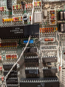
I have removed all the 74HS257 chips, all tested OK. If I want to disable upper ram completely, do I need to remove the 00 and the one next to it as well?
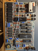
This is the state of the board now:
Also any thoughts on the TR5 being NPN vs PNP? I know that video is an earlier issue, but my tests were the opposite for TR5 when measuring the collector and emitter.
TR5 is a 213, on the 4b schematics, says it should be a 315, one is NPN and the other is PNP so the collector and emitter is swapped?
Trying to save the chips, but this last 257 was a bugger, and almost cut it out. Keeping them for testing only.
I have removed all the 74HS257 chips, all tested OK. If I want to disable upper ram completely, do I need to remove the 00 and the one next to it as well?
This is the state of the board now:
Also any thoughts on the TR5 being NPN vs PNP? I know that video is an earlier issue, but my tests were the opposite for TR5 when measuring the collector and emitter.
TR5 is a 213, on the 4b schematics, says it should be a 315, one is NPN and the other is PNP so the collector and emitter is swapped?
-
1024MAK
- Bugaboo
- Posts: 3118
- Joined: Wed Nov 15, 2017 2:52 pm
- Location: Sunny Somerset in the U.K. in Europe
Re: Stuck with repair of Spectrum+
A ZTX213 is the correct specified transistor for TR5, the ‘315’ is yet another error in the schematic diagrams... (yes, there are lots of errors).speccyplus wrote: ↑Wed Apr 22, 2020 2:48 pm So I am taking a closer look at all the previous replaced parts. This makes me take a closer look at the transistors.
TR4 is the correct part, a 650
TR5 is a 213, on the 4b schematics, says it should be a 315, one is NPN and the other is PNP so the collector and emitter is swapped? Not sure on these parts. However my voltages look OK when I check on the ram. This was the one that was confusing me before doing testing and seemed backwards compared to others.
TR4 can be a ZXT650, ZTX651 or a ZXT653.
Most boards use ZTX313 transistors, but some use other types. TR1 and TR2 are the final stages in the analogue (composite) video stages. If your video signal is acceptable (disregarding the multicoloured mess caused by the fault on the processor side of the board), then they are fine. BC548C or BC549C are often used for replacements, as ZTX313 transistors are obsolete.speccyplus wrote: ↑Wed Apr 22, 2020 2:48 pmFor TR2 I have a 548, not a 313. I can't see TR1 but looks physically the same and they look different than all the other transistors, packaging is larger and round. So I assume replaced at the same time.
Sinclair used multiple manufacturers and they used multiple compatible parts in order to keep the price low. So it’s not unusual to find suitable alternative parts used, either when originally made, or as a result of having been serviced or repaired.
Mark
“There are four lights!”
Step up to red alert. Sir, are you absolutely sure? It does mean changing the bulb
Looking forward to summer later in the year.
-
1024MAK
- Bugaboo
- Posts: 3118
- Joined: Wed Nov 15, 2017 2:52 pm
- Location: Sunny Somerset in the U.K. in Europe
Re: Stuck with repair of Spectrum+
Ahh, a Mr Zigg video. They are good. Although I can’t get used to his voice.
Mark
Mark
“There are four lights!”
Step up to red alert. Sir, are you absolutely sure? It does mean changing the bulb
Looking forward to summer later in the year.
-
1024MAK
- Bugaboo
- Posts: 3118
- Joined: Wed Nov 15, 2017 2:52 pm
- Location: Sunny Somerset in the U.K. in Europe
Re: Stuck with repair of Spectrum+
The 74 series logic chips used in positions IC23 and IC24 are normally very reliable (they are the simplest digital chips on the board). And IC24 is needed to control IC3 and IC4 for the lower RAM.speccyplus wrote: ↑Wed Apr 22, 2020 4:04 pm If I want to disable upper ram completely, do I need to remove the 00 and the one next to it as well?
To fully eliminate the upper DRAM (the TMS4532) chips, the only sure fire way, is to remove them. If you remove only IC23 you will leave the DRAM control inputs (RAS and CAS floating, which would not be good. And if one of the TMS4532 chips is affecting the data bus, you are no better off than the method I outlined a few days ago in an earlier post.
Indeed, with IC25 and IC26 missing, the address inputs to the upper DRAM chips are already floating. If they are disabled as per my earlier post, this does not matter.
Mark
“There are four lights!”
Step up to red alert. Sir, are you absolutely sure? It does mean changing the bulb
Looking forward to summer later in the year.
-
speccyplus
- Drutt
- Posts: 46
- Joined: Wed Apr 15, 2020 5:41 pm
Re: Stuck with repair of Spectrum+
Ok, so other than for the fun of removing and testing chips, I will wait for my CPU to show up.
Will read up on doing some tests with the oscilloscope.
Will read up on doing some tests with the oscilloscope.
-
speccyplus
- Drutt
- Posts: 46
- Joined: Wed Apr 15, 2020 5:41 pm
Re: Stuck with repair of Spectrum+
Ok, got some parts in over the weekend.
Same results.
Swapped CPU. Same results.
This at this point I assume it is upper RAM or the ULA maybe?
The one ram chip that started the whole investigation was pretty darn hot, it was the second from the bottom left. I know the RAM is all tied into the ULA.
The other option is to start cutting out the upper ram.
Or ROM issues?
Anyone have any more thoughts?
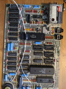
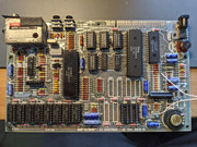
Here is the board now:
- 2 extra ram chips for lower ram.
CPU
Cap Kit
Same results.
Swapped CPU. Same results.
This at this point I assume it is upper RAM or the ULA maybe?
The one ram chip that started the whole investigation was pretty darn hot, it was the second from the bottom left. I know the RAM is all tied into the ULA.
The other option is to start cutting out the upper ram.
Or ROM issues?
Anyone have any more thoughts?
Here is the board now:
-
speccyplus
- Drutt
- Posts: 46
- Joined: Wed Apr 15, 2020 5:41 pm
Re: Stuck with repair of Spectrum+
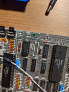
Ok, removed all the upper ram chips, last person to work on this used too hot an iron, lots of burned through holes and I have to deal with lifted traces Started some bodge wire work on the bottom row, top needs it too.
Scoured the area for any shorts I could find.
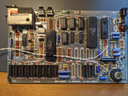
Anyways, after the board was liberated of all its upper ram, it looked like this:
And did the same thing as before.
So I removed the lower ram, this looks a bit better as I saw on other videos the way it should behave with no ram.
I will post a video shortly.
Scoured the area for any shorts I could find.
Anyways, after the board was liberated of all its upper ram, it looked like this:
And did the same thing as before.
So I removed the lower ram, this looks a bit better as I saw on other videos the way it should behave with no ram.
I will post a video shortly.
-
speccyplus
- Drutt
- Posts: 46
- Joined: Wed Apr 15, 2020 5:41 pm
Re: Stuck with repair of Spectrum+
Here is what it should look like with no ram:
https://www.youtube.com/watch?v=izcGFap8HGI
And here is what I get:
[media]https://streamable.com/g7frud[/media]
It looks like something kinda works, but still hangs... Similar but not the same...
https://www.youtube.com/watch?v=izcGFap8HGI
And here is what I get:
[media]https://streamable.com/g7frud[/media]
It looks like something kinda works, but still hangs... Similar but not the same...