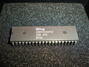
Got this one, slightly faster at 6mhz than the 4mhz one in there now.
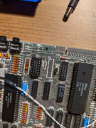

Pins 14, 15 and 16 should be shorted together...speccyplus wrote: ↑Wed Apr 22, 2020 1:50 am Spent some more time scouring the board, I see nothing bridged on the bottom, except 3 pins that look like they are soldered together on the IC 14 chip, pins 13,14 and 15 I believe, on the bottom. This was the replaced chip by previous owner.
Thanks!Firefox wrote: ↑Wed Apr 22, 2020 1:04 pmPins 14, 15 and 16 should be shorted together...speccyplus wrote: ↑Wed Apr 22, 2020 1:50 am Spent some more time scouring the board, I see nothing bridged on the bottom, except 3 pins that look like they are soldered together on the IC 14 chip, pins 13,14 and 15 I believe, on the bottom. This was the replaced chip by previous owner.
(edit) That looks correct in your photo of the PCB underside.

I normally recommend that unless the chip being removed needs to be saved, that all the pins are cut as near to the top of the plastic package as possible. Then the pin can be moved with long nose pliers while keeping the solder molten with the iron. If the bottom is not bent over, you could gently pull it out. Obviously if the bottom is bent over, it’s not that simplespeccyplus wrote: ↑Wed Apr 22, 2020 1:50 am I hate that all the pins are not clipped, but folded over, pain to solder suck, have to bend them and risk damage to the pads on the bottom. Second one took forever to pull so I would not damage the board.
7400 series and 74LSxxx series have inputs that tend to float high if left unconnected (but this is definitely not recommended practice).speccyplus wrote: ↑Wed Apr 22, 2020 1:50 amI don't think the LS257 I had would work, since HC I think float high and and the LS use more power.
speccyplus wrote: ↑Wed Apr 22, 2020 1:50 am Spent some more time scouring the board, I see nothing bridged on the bottom, except 3 pins that look like they are soldered together on the IC 14 chip, pins 13,14 and 15 I believe, on the bottom.[/url]
That’s as per the design. IC14 is the video colour encoder.
Mark
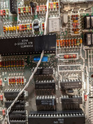
A ZTX213 is the correct specified transistor for TR5, the ‘315’ is yet another error in the schematic diagrams... (yes, there are lots of errors).speccyplus wrote: ↑Wed Apr 22, 2020 2:48 pm So I am taking a closer look at all the previous replaced parts. This makes me take a closer look at the transistors.
TR4 is the correct part, a 650
TR5 is a 213, on the 4b schematics, says it should be a 315, one is NPN and the other is PNP so the collector and emitter is swapped? Not sure on these parts. However my voltages look OK when I check on the ram. This was the one that was confusing me before doing testing and seemed backwards compared to others.
Most boards use ZTX313 transistors, but some use other types. TR1 and TR2 are the final stages in the analogue (composite) video stages. If your video signal is acceptable (disregarding the multicoloured mess caused by the fault on the processor side of the board), then they are fine. BC548C or BC549C are often used for replacements, as ZTX313 transistors are obsolete.speccyplus wrote: ↑Wed Apr 22, 2020 2:48 pmFor TR2 I have a 548, not a 313. I can't see TR1 but looks physically the same and they look different than all the other transistors, packaging is larger and round. So I assume replaced at the same time.
The 74 series logic chips used in positions IC23 and IC24 are normally very reliable (they are the simplest digital chips on the board). And IC24 is needed to control IC3 and IC4 for the lower RAM.speccyplus wrote: ↑Wed Apr 22, 2020 4:04 pm If I want to disable upper ram completely, do I need to remove the 00 and the one next to it as well?
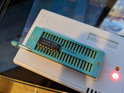
The ROM is type 23128, which is similar to a 27128 EPROM but the ROM has two CS chip select / chip enable control signal input pins, unlike the EPROM which has only one. Both have an OE output enable. Or the ROM could have three CS chip select / chip enable control signal input pins. It depends on which ROM from which manufacturer was fitted.speccyplus wrote: ↑Wed Apr 29, 2020 10:08 pm I just went and socket the rom, hoping my reader can read it. Does anyone know the specs for that chip?
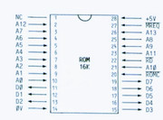
If that pinout is accurate then the ROM links are correct in the "H" configuration, as they are in your latest photo.