C74 - should be 4.7uF, was 22uF -
C27 - should be 1uF, was 4.7uF - that will just give a slightly longer reset pulse to the Z80.
Did the person who you got this from wear a stetson?
Mark

Haha, I couldn't tell you unfortunately but it could be the case.1024MAK wrote: ↑Sun May 03, 2020 12:37 am C80 - should be 22uF, was 1uF -this will affect the power output of the DC/DC converter
C74 - should be 4.7uF, was 22uF -
C27 - should be 1uF, was 4.7uF - that will just give a slightly longer reset pulse to the Z80.
Did the person who you got this from wear a stetson?
Mark

What, and it didn't work?HappyLittleDiodes wrote: ↑Sun May 03, 2020 9:02 pm My replacement Z80 was actually a Z84C20 with is a PIO chip.
I'm impressed that anything happened.dfzx wrote: ↑Mon May 04, 2020 9:18 amWhat, and it didn't work?HappyLittleDiodes wrote: ↑Sun May 03, 2020 9:02 pm My replacement Z80 was actually a Z84C20 with is a PIO chip.
Try powering up a ZX Spectrum with the Z80 missing...HappyLittleDiodes wrote: ↑Mon May 04, 2020 11:39 amI'm impressed that anything happened.
I got the screen shown in the post above and the blocks were changing.
The chip did get quite hot though...
It got me thinking, could you make a simulation so accurate that you could predict this behaviour if you put this chip into a working spectrum?
Copper tape? You mean the desoldering stuff?HappyLittleDiodes wrote: ↑Mon May 04, 2020 8:04 pm Time to put it away until the copper tape arrives...
No it's a sticky copper tape for electronic repairs. You tidy up the damage, stick this over and solder it in.dfzx wrote: ↑Tue May 05, 2020 10:54 amCopper tape? You mean the desoldering stuff?HappyLittleDiodes wrote: ↑Mon May 04, 2020 8:04 pm Time to put it away until the copper tape arrives...

Something else I never knew existed.HappyLittleDiodes wrote: ↑Tue May 05, 2020 11:00 am No it's a sticky copper tape for electronic repairs. You tidy up the damage, stick this over and solder it in.
I tried to make the link with a small wire but buggered it up

Did you use a heat gun to help with removing the chips?speccyplus wrote: ↑Wed May 06, 2020 2:26 pm
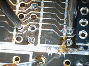
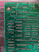
For you feel better pleasure. Top side just had a few traces, bottom was a disaster ground. I did the full nuke on removing all the upper ram and logic chips and for some reason that section gave me all the trouble (ram). Rest was 98% fine. Good news is I have a fully socketed board once I get that last two sockets in.
Not my best work or my most proud, I have never had so much trouble desoldering components than on this board being so fragile.
So many pads came off on the 32k section from previous damage. Not needed as they were not connected to anything, but still. Next time I will try the thin wire repairs hidden by the socket, that I have seen folks do. You need a steady hand...
https://www.youtube.com/watch?v=KRSQOOY67DU
I have a power vacuum solder sucker, and it was horrible, it usually works quite well. I had better luck with a manual sucker, and cleaning the holes out that way.HappyLittleDiodes wrote: ↑Wed May 06, 2020 2:53 pmDid you use a heat gun to help with removing the chips?speccyplus wrote: ↑Wed May 06, 2020 2:26 pm
For you feel better pleasure. Top side just had a few traces, bottom was a disaster ground. I did the full nuke on removing all the upper ram and logic chips and for some reason that section gave me all the trouble (ram). Rest was 98% fine. Good news is I have a fully socketed board once I get that last two sockets in.
Not my best work or my most proud, I have never had so much trouble desoldering components than on this board being so fragile.
So many pads came off on the 32k section from previous damage. Not needed as they were not connected to anything, but still. Next time I will try the thin wire repairs hidden by the socket, that I have seen folks do. You need a steady hand...
https://www.youtube.com/watch?v=KRSQOOY67DU
I find it makes the actual removal a lot smoother, but you still have to take the time to get as much solder out as possible!
I'll let you know how I get on using the tape