Before you buy a multimeter, have you tried using a phono to phono lead from the TV out on the ZX Spectrum to the composite video input (the socket normally coloured or marked yellow) on your TV?
And have you popped the metal cover off the modulator? The modulator is the silver tin can in the rear left hand corner with the TV out socket on it. To remove the cover, use a flat bladed screwdriver to lever up the top part of the metal case. If you need help, let us know. Never lever against any other component or against the PCB.
Mark
Spectrum+ No picture
-
1024MAK

- Bugaboo
- Posts: 3114
- Joined: Wed Nov 15, 2017 2:52 pm
- Location: Sunny Somerset in the U.K. in Europe
Re: Spectrum+ No picture
“There are four lights!”
Step up to red alert. Sir, are you absolutely sure? It does mean changing the bulb
Looking forward to summer later in the year.
-
spooney100
- Drutt
- Posts: 9
- Joined: Wed Jul 22, 2020 1:22 pm
Re: Spectrum+ No picture
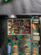
I've tried phono leads to no avail. I have checked inside the modulator and it looks ok to me but I wouldn't know if anythings up with it to be honest so I've attached a pic for you to check.
My friends getting a multimeter, not sure how good its gong to be but its a BEVA digital multimeter apparently.
My friends getting a multimeter, not sure how good its gong to be but its a BEVA digital multimeter apparently.
-
1024MAK
- Bugaboo
- Posts: 3114
- Joined: Wed Nov 15, 2017 2:52 pm
- Location: Sunny Somerset in the U.K. in Europe
Re: Spectrum+ No picture
The photo is fine.
That modulator has definitely not been bypassed, so no composite video modification has been done.
Definitely need the services of a multimeter. If your friend has a logic probe or better yet, an oscilloscope, tell him that they would be helpful as well...
First, whatever the measurement, the negative / black meter lead / probe has to connect to a 0V/GND (ground) point (ground in this context does NOT mean mains earth, but the circuit common). Good places are the metal tab of the 7805 voltage regulator (the thing that the metal heatsink is attached to) or the case of the modulator.
Set the multimeter to the 20V (or equivalent) DC range. The computer does need to be powered up for these tests.
With the positive / red probe, carefully (don’t slip) test the following points:
Mark
That modulator has definitely not been bypassed, so no composite video modification has been done.
Definitely need the services of a multimeter. If your friend has a logic probe or better yet, an oscilloscope, tell him that they would be helpful as well...
First, whatever the measurement, the negative / black meter lead / probe has to connect to a 0V/GND (ground) point (ground in this context does NOT mean mains earth, but the circuit common). Good places are the metal tab of the 7805 voltage regulator (the thing that the metal heatsink is attached to) or the case of the modulator.
Set the multimeter to the 20V (or equivalent) DC range. The computer does need to be powered up for these tests.
With the positive / red probe, carefully (don’t slip) test the following points:
- IC14 (LM1889) pins 14, 15, 16 (expected voltage is between +11V and +12V). DIL chips (as fitted to a ZX Spectrum) count anti-clockwise, see this topic for an example showing the Z80A microprocessor.
We don’t have a board layout for the issue 4S board, but it is based on the earlier issue 4A, here is the layout for the issue 4A - Positive lead of capacitor C44 (expected voltage is +12V). This type of capacitor is an electrolytic, they have a black or white band marked with minus signs (-), the band will have arrows pointing to the negative lead of the capacitor. There may be a plus symbol marked on the PCB next to the positive (+) lead.
- Positive lead of capacitor C45 (expected voltage is between +11V and +12V).
C44 and C45 are in the front centre area of the board. - Wire going into the modulator nearest to the front of the board (expected voltage is +5V). This wire is on the left hand side of the board / modulator case.
- Wire going into the modulator nearest to the back of the board. Again on the left hand side.
Mark
“There are four lights!”
Step up to red alert. Sir, are you absolutely sure? It does mean changing the bulb
Looking forward to summer later in the year.
-
spooney100
- Drutt
- Posts: 9
- Joined: Wed Jul 22, 2020 1:22 pm
Re: Spectrum+ No picture
Hi Mark
I've tested the connections and it looks like theres a few issues. the Voltage in each are as follows.
IC14 :- 14 - 11.55, 15 - 3.53, 16 - 11.51
C44 :- 11.88
C45 :- 11.55
Modulator front Wire :- 3.52
Modulator Rear wire :- 0
I've tested the connections and it looks like theres a few issues. the Voltage in each are as follows.
IC14 :- 14 - 11.55, 15 - 3.53, 16 - 11.51
C44 :- 11.88
C45 :- 11.55
Modulator front Wire :- 3.52
Modulator Rear wire :- 0
-
spooney100
- Drutt
- Posts: 9
- Joined: Wed Jul 22, 2020 1:22 pm
Re: Spectrum+ No picture
Ignore my last response Mark, I checked the wring pins on the IC14.
The correct readings are below.
IC14 :- 14 - 11.53, 15 - 11.53, 16 - 11.53
C44 :- 11.88
C45 :- 11.55
Modulator front Wire :- 3.52
Modulator Rear wire :- 0
The correct readings are below.
IC14 :- 14 - 11.53, 15 - 11.53, 16 - 11.53
C44 :- 11.88
C45 :- 11.55
Modulator front Wire :- 3.52
Modulator Rear wire :- 0
-
1024MAK
- Bugaboo
- Posts: 3114
- Joined: Wed Nov 15, 2017 2:52 pm
- Location: Sunny Somerset in the U.K. in Europe
Re: Spectrum+ No picture
So the 12V supplies and devices are fine.
But the analogue 5V is low and there is no video signal.
The video to the modulator is via the rear wire and should be around 2 to 3V DC when using most multimeters.
Measure the voltage on both leads of resistor R64 (15Ω). It’s around the middle of the left hand row of resistors.
Same on resistors R51 (2.2kΩ) (near TR1) and R48 (4.7kΩ) (in the same row of resistors as R64).
Are TR1 and TR2 cool or is one warm? They are near the modulator.
Mark
But the analogue 5V is low and there is no video signal.
I would expect between 4.5V and 5V on the front wire to the modulator, for example on a issue 3 board, I get 4.94V. This is the 5V supply to the modulator and to the video output stage transistors.Modulator front Wire :- 3.52
Modulator Rear wire :- 0
The video to the modulator is via the rear wire and should be around 2 to 3V DC when using most multimeters.
Measure the voltage on both leads of resistor R64 (15Ω). It’s around the middle of the left hand row of resistors.
Same on resistors R51 (2.2kΩ) (near TR1) and R48 (4.7kΩ) (in the same row of resistors as R64).
Are TR1 and TR2 cool or is one warm? They are near the modulator.
Mark
“There are four lights!”
Step up to red alert. Sir, are you absolutely sure? It does mean changing the bulb
Looking forward to summer later in the year.
-
spooney100
- Drutt
- Posts: 9
- Joined: Wed Jul 22, 2020 1:22 pm
Re: Spectrum+ No picture
Readings are as follows:-
R64:- L - 4.90, R 4.77
R51:- L 3.75, r 0.79
R48:- L 1.95, R 1.39
TR1 is cool but TR2 is hot.
R64:- L - 4.90, R 4.77
R51:- L 3.75, r 0.79
R48:- L 1.95, R 1.39
TR1 is cool but TR2 is hot.
-
1024MAK
- Bugaboo
- Posts: 3114
- Joined: Wed Nov 15, 2017 2:52 pm
- Location: Sunny Somerset in the U.K. in Europe
Re: Spectrum+ No picture
TR2 should not be hot.
If you can use a soldering Iron, carefully disconnect both wires going into the modulator from the PCB. Then power up and see if TR2 still gets hot. If it does, there is a good chance that it’s defective. In which case it will need to be replaced with a new transistor.
Mark
If you can use a soldering Iron, carefully disconnect both wires going into the modulator from the PCB. Then power up and see if TR2 still gets hot. If it does, there is a good chance that it’s defective. In which case it will need to be replaced with a new transistor.
Mark
“There are four lights!”
Step up to red alert. Sir, are you absolutely sure? It does mean changing the bulb
Looking forward to summer later in the year.
-
spooney100
- Drutt
- Posts: 9
- Joined: Wed Jul 22, 2020 1:22 pm
Re: Spectrum+ No picture
Hi Mark
Yeah it looks like TR2s defective, I've disconnected the 2 wires going into the modulator and its still getting hot. I'll have to get it replaced. Thanks for all the help. Its massively appreciated.
Yeah it looks like TR2s defective, I've disconnected the 2 wires going into the modulator and its still getting hot. I'll have to get it replaced. Thanks for all the help. Its massively appreciated.
-
1024MAK
- Bugaboo
- Posts: 3114
- Joined: Wed Nov 15, 2017 2:52 pm
- Location: Sunny Somerset in the U.K. in Europe
Re: Spectrum+ No picture
Once TR2 has been removed, with the power disconnected from the computer, use the resistance ranges on your multimeter to test the various resistors in that area as well.
Mark
Mark
“There are four lights!”
Step up to red alert. Sir, are you absolutely sure? It does mean changing the bulb
Looking forward to summer later in the year.