Hi all
I recently got hold of a JVC PVM for all my old computers and consoles and am using a multi RCA adapter to route them all through, however I can't get my +3 connected since there aren't any RCA adapters available for it (due to it not supporting RGB, I'm informed, although I still don't understand how you can still use a scart adapter since I thought that was RGB too). I even tried an aerial to BNC adapter to try and run the aerial connector to the PVM, but that just gave me a blank screen.
Anyone have any experience with hooking a +3 to a PVM?
cheers!
Spectrum +3 to a PVM with BNC sockets
-
cunningmunki
- Drutt
- Posts: 4
- Joined: Thu Aug 20, 2020 2:42 pm
-
1024MAK

- Bugaboo
- Posts: 3123
- Joined: Wed Nov 15, 2017 2:52 pm
- Location: Sunny Somerset in the U.K. in Europe
Re: Spectrum +3 to a PVM with BNC sockets
I don’t have a JVC PVM, but I do know about the video systems used by the ZX Spectrum computers.
There is more than one RGB system.
The +3 does use a RGB video system, but not a standard analogue RGB system. In the custom built SCART leads, additional electronic components are fitted to convert the video signals to a suitable signal for (some) SCART equipped TVs.
What does the JVC PVM require?
It’s unlikely that you will find a ready made cable, cables or adapter. Are you able to solder?
Mark
“There are four lights!”
Step up to red alert. Sir, are you absolutely sure? It does mean changing the bulb
Looking forward to summer later in the year.
-
cunningmunki
- Drutt
- Posts: 4
- Joined: Thu Aug 20, 2020 2:42 pm
Re: Spectrum +3 to a PVM with BNC sockets
It's a single BNC video connector (not multiple RGB like Sony PVMs) but it also has s-video inputs. I tried a scart to s-video converter which worked but only gave me a black and white image (although it's probably more accurate to say it only gave me the whites, there were no greys).
I can solder and modded my Atari 2600 with a composite cable. I've been looking for a mod for the +3 but can only find mods for the original 48k
I can solder and modded my Atari 2600 with a composite cable. I've been looking for a mod for the +3 but can only find mods for the original 48k
-
1024MAK
- Bugaboo
- Posts: 3123
- Joined: Wed Nov 15, 2017 2:52 pm
- Location: Sunny Somerset in the U.K. in Europe
Re: Spectrum +3 to a PVM with BNC sockets
Ahh, are you saying that your PVM has a composite (or “baseband”) input?
Mark
Mark
“There are four lights!”
Step up to red alert. Sir, are you absolutely sure? It does mean changing the bulb
Looking forward to summer later in the year.
-
cunningmunki
- Drutt
- Posts: 4
- Joined: Thu Aug 20, 2020 2:42 pm
Re: Spectrum +3 to a PVM with BNC sockets
Yep, two composite in/outs and one s-video in/out. Here's the manual: https://www.manualslib.com/manual/81893 ... e=6#manual
-
1024MAK
- Bugaboo
- Posts: 3123
- Joined: Wed Nov 15, 2017 2:52 pm
- Location: Sunny Somerset in the U.K. in Europe
Re: Spectrum +3 to a PVM with BNC sockets
As standard, the +3 machine does not have a composite video output. However, if you can solder, it’s easy enough to modify it.
Details are on this web page. Note that any reasonable small signal NPN transistor can be used, such as a BC547, BC548 or BC549 plus many, many more.
If you prefer not to alter the existing output on the monitor DIN socket, instead you can use the existing phono socket on the modulator. Remove the lid, then desolder the existing connection to the inner pin of the phono connector (a resistor lead). Also desolder the +5V feed wire and the video input wire for the modulator from the PCB and tuck them away so they can’t flap around and short against anything.
Now route the output signal from the modification to the centre pin of the phono socket. You can go via one of the existing feed through holes in the modulator.
Mark
“There are four lights!”
Step up to red alert. Sir, are you absolutely sure? It does mean changing the bulb
Looking forward to summer later in the year.
-
cunningmunki
- Drutt
- Posts: 4
- Joined: Thu Aug 20, 2020 2:42 pm
Re: Spectrum +3 to a PVM with BNC sockets
Sorry, I understood very little of that. I've only ever done mods with kits with very detailed instructions and have no experience making a circuit board from scratch (not to mention the time to actually do it). Thanks, though.
So is there no way to get an aerial signal into it?
So is there no way to get an aerial signal into it?
Re: Spectrum +3 to a PVM with BNC sockets
A video monitor is not a TV so doesn't have a UHF tuner.
You don't need to build the circuit up on a board for the composite mod as it's so simple, you can just solder the components directly together and insulate everything with sleeving.
You don't need to build the circuit up on a board for the composite mod as it's so simple, you can just solder the components directly together and insulate everything with sleeving.
-
1024MAK
- Bugaboo
- Posts: 3123
- Joined: Wed Nov 15, 2017 2:52 pm
- Location: Sunny Somerset in the U.K. in Europe
Re: Spectrum +3 to a PVM with BNC sockets
The circuit is here.
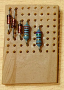
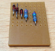
Here’s a board I made in less than an hour this evening:
Start with the diodes and the resistors...
Then after these are soldered in, add the wires and the transistor. When soldering the transistor, allow at least one minute between soldering each leg so it does not get too hot.

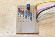
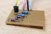
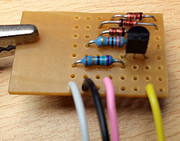
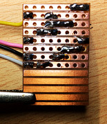
The board used is a piece of copper strip-board that was cut to size. No track cuts are required.
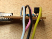
The wire colours are:
Yellow = +12V from pin 11 of the TEA2000
Pink = video in from pin 6 of the TEA2000
Black = 0V/GND
White = composite video out to either pin 1 on the DIN socket or to the modulator phono centre connection.
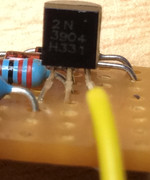
The components are (left to right as shown in the third and fourth photos):
D4 = 1N4148 signal diode
D8 = 1N4148 signal diode
D7 = 1N4148 signal diode
R10 = 2.2kΩ (2k2) resistor (I used a 250mW 5% metal film type as that is what I had to hand, but a ¼W 5% carbon film type is fine)
TR4 = 2N3904 small signal NPN transistor (if a different type is used, check the lead-out, as it may also be different)
R2 = 75Ω (75R) resistor (I used a 0.6mW 1% metal film type as that is what I had to hand, but a ¼W 5% carbon film type is fine).
Mark
Here’s a board I made in less than an hour this evening:
Start with the diodes and the resistors...
Then after these are soldered in, add the wires and the transistor. When soldering the transistor, allow at least one minute between soldering each leg so it does not get too hot.
The board used is a piece of copper strip-board that was cut to size. No track cuts are required.
The wire colours are:
Yellow = +12V from pin 11 of the TEA2000
Pink = video in from pin 6 of the TEA2000
Black = 0V/GND
White = composite video out to either pin 1 on the DIN socket or to the modulator phono centre connection.
The components are (left to right as shown in the third and fourth photos):
D4 = 1N4148 signal diode
D8 = 1N4148 signal diode
D7 = 1N4148 signal diode
R10 = 2.2kΩ (2k2) resistor (I used a 250mW 5% metal film type as that is what I had to hand, but a ¼W 5% carbon film type is fine)
TR4 = 2N3904 small signal NPN transistor (if a different type is used, check the lead-out, as it may also be different)
R2 = 75Ω (75R) resistor (I used a 0.6mW 1% metal film type as that is what I had to hand, but a ¼W 5% carbon film type is fine).
Mark
“There are four lights!”
Step up to red alert. Sir, are you absolutely sure? It does mean changing the bulb
Looking forward to summer later in the year.