Before doing any further work on it, and certainly before replacing any chips, or cutting any chip legs, you should follow the instructions here over on World of Spectrum, to disable the upper RAM chips. Don't worry about oscilloscope tests that are also in that post.
Disabling the upper RAM may allow the machine to start up as a 16k model. That may then give you a better idea of the problem.
Mark
Blank screen issue...
-
1024MAK

- Bugaboo
- Posts: 3123
- Joined: Wed Nov 15, 2017 2:52 pm
- Location: Sunny Somerset in the U.K. in Europe
Re: Blank screen issue...
“There are four lights!”
Step up to red alert. Sir, are you absolutely sure? It does mean changing the bulb
Looking forward to summer later in the year.
-
Ast A. Moore

- Rick Dangerous
- Posts: 2641
- Joined: Mon Nov 13, 2017 3:16 pm
Re: Blank screen issue...
Ha! Didn’t know about this trick. Awesome.
Every man should plant a tree, build a house, and write a ZX Spectrum game.
Author of A Yankee in Iraq, a 50 fps shoot-’em-up—the first game to utilize the floating bus on the +2A/+3,
and zasm Z80 Assembler syntax highlighter.
Author of A Yankee in Iraq, a 50 fps shoot-’em-up—the first game to utilize the floating bus on the +2A/+3,
and zasm Z80 Assembler syntax highlighter.
Re: Blank screen issue...
Cool, just reading over everyhting now including the last one RE: Dissabling the upper ram.
I was wondering, if there is an issue with any of the ram, do the individual chips ever over heat at all? I checked them and they all seemed cold (same temp). Just wondered if that would have been an indication of an issue.
Thanks
R
I was wondering, if there is an issue with any of the ram, do the individual chips ever over heat at all? I checked them and they all seemed cold (same temp). Just wondered if that would have been an indication of an issue.
Thanks
R
Re: Blank screen issue...
Also, in reading all the info, the capacitors were mentioned in relation to the ram.
Is this something I may also need to consider? Or do you think that would be unlikely?
Thanks
Rps
Is this something I may also need to consider? Or do you think that would be unlikely?
Thanks
Rps
-
1024MAK
- Bugaboo
- Posts: 3123
- Joined: Wed Nov 15, 2017 2:52 pm
- Location: Sunny Somerset in the U.K. in Europe
Re: Blank screen issue...
The 'lower' RAM are 4116 DRAM (16k bits each) chips which run warm, with some running warmer than others. Sometimes when they fail, they may get hotter. But only if the supply can supply the extra power. Otherwise the switching transistor for the +12V and -5V dies.
The 'upper' RAM are 32k bits each (various part numbers). They are 4164 DRAM (64k bits each) chips which are only half used, these being cheaper at the time, as a half working 64k bit chip could be sold as a 32k bit chip. These are more advanced than the earlier 4116 DRAM design. They run much cooler and most of the time, it is not possible to detect a faulty chip by feeling the temperature with your finger.
Renewal of the electrolytic capacitors is recommended so that the DC/DC inverter/converter on the main board is reliable, and to minimise the noise on the video screen. It is less important for the upper RAM. It is unlikely that a capacitor failure will have caused a failure of the upper RAM.
But we will be in a better position to advise you after you have tried the disable upper RAM test.
Mark
“There are four lights!”
Step up to red alert. Sir, are you absolutely sure? It does mean changing the bulb
Looking forward to summer later in the year.
Re: Blank screen issue...
That's good, hoping to run that test laser this evening/ tomorrow morning.
The screen that I do have booting up does tend to have quite a bit of noise on it. I would say some of my other consoles do too but I don't think it is as bad as on this one.
Any way will try run the test and see from there.
Thanks
Amy
The screen that I do have booting up does tend to have quite a bit of noise on it. I would say some of my other consoles do too but I don't think it is as bad as on this one.
Any way will try run the test and see from there.
Thanks
Amy
-
Ast A. Moore
- Rick Dangerous
- Posts: 2641
- Joined: Mon Nov 13, 2017 3:16 pm
Re: Blank screen issue...
Is your Speccy composite-modded or are you using the original RF output?
Every man should plant a tree, build a house, and write a ZX Spectrum game.
Author of A Yankee in Iraq, a 50 fps shoot-’em-up—the first game to utilize the floating bus on the +2A/+3,
and zasm Z80 Assembler syntax highlighter.
Author of A Yankee in Iraq, a 50 fps shoot-’em-up—the first game to utilize the floating bus on the +2A/+3,
and zasm Z80 Assembler syntax highlighter.
Re: Blank screen issue...
Hi,
Do you know what number pin the +5v is on the IC23? Can’t find a pin diagram that shows it.
Thanks
RPS
Do you know what number pin the +5v is on the IC23? Can’t find a pin diagram that shows it.
Thanks
RPS
-
Ast A. Moore
- Rick Dangerous
- Posts: 2641
- Joined: Mon Nov 13, 2017 3:16 pm
Re: Blank screen issue...
Pin 8 is VDD, pin 16 is ground: http://pdf1.alldatasheet.com/datasheet- ... 4164B.html
Every man should plant a tree, build a house, and write a ZX Spectrum game.
Author of A Yankee in Iraq, a 50 fps shoot-’em-up—the first game to utilize the floating bus on the +2A/+3,
and zasm Z80 Assembler syntax highlighter.
Author of A Yankee in Iraq, a 50 fps shoot-’em-up—the first game to utilize the floating bus on the +2A/+3,
and zasm Z80 Assembler syntax highlighter.
-
1024MAK
- Bugaboo
- Posts: 3123
- Joined: Wed Nov 15, 2017 2:52 pm
- Location: Sunny Somerset in the U.K. in Europe
Re: Blank screen issue...
On IC23 (a 74LS32, quad 2-input OR gates), pin 14 is Vcc (+5V). 0V/GND is on pin 7.
I should point out that the method given in the earlier post about how to disable the 'upper' RAM only applies to issue 2 to issue 4S boards. It does not apply to issue 5 to issue 6 boards.
I've put a pin-out of a 74LS32 (IC23), and a schematic of an issue 4 on my Flickr account here
Mark
Last edited by 1024MAK on Sun Jun 17, 2018 11:41 pm, edited 1 time in total.
“There are four lights!”
Step up to red alert. Sir, are you absolutely sure? It does mean changing the bulb
Looking forward to summer later in the year.
-
1024MAK
- Bugaboo
- Posts: 3123
- Joined: Wed Nov 15, 2017 2:52 pm
- Location: Sunny Somerset in the U.K. in Europe
Re: Blank screen issue...
Okay, how much beer have you drunk?Ast A. Moore wrote: ↑Sun Jun 17, 2018 8:02 pmPin 8 is VDD, pin 16 is ground: http://pdf1.alldatasheet.com/datasheet- ... 4164B.html
Mark
“There are four lights!”
Step up to red alert. Sir, are you absolutely sure? It does mean changing the bulb
Looking forward to summer later in the year.
Re: Blank screen issue...
Hi,
It is a 4s model.
So I did pins 5 to 14 and nothing happened. I did pin 14 to ground (7 was it?) that shuts the machine off and then comes back on when removed.
I accidentally touched one of the other pins last night and it brought up lots of colou blocks which then disappear when power is removed.
Does any of this mean anything? I read the rest of the post but it started to go over my head. So I am hoping this can mow tell me what part needs replacing!!!
Thank you
Amy
-
Ast A. Moore
- Rick Dangerous
- Posts: 2641
- Joined: Mon Nov 13, 2017 3:16 pm
Re: Blank screen issue...
Oh, crap, it’s a bloody OR gate. I misread the number as IC22. No beer. Otherwise I’d have stayed within odd numbers. Just a long day.1024MAK wrote: ↑Sun Jun 17, 2018 11:40 pmOkay, how much beer have you drunk?Ast A. Moore wrote: ↑Sun Jun 17, 2018 8:02 pm Pin 8 is VDD, pin 16 is ground: http://pdf1.alldatasheet.com/datasheet- ... 4164B.html
Every man should plant a tree, build a house, and write a ZX Spectrum game.
Author of A Yankee in Iraq, a 50 fps shoot-’em-up—the first game to utilize the floating bus on the +2A/+3,
and zasm Z80 Assembler syntax highlighter.
Author of A Yankee in Iraq, a 50 fps shoot-’em-up—the first game to utilize the floating bus on the +2A/+3,
and zasm Z80 Assembler syntax highlighter.
-
Ast A. Moore
- Rick Dangerous
- Posts: 2641
- Joined: Mon Nov 13, 2017 3:16 pm
Re: Blank screen issue...
You’ll need to solder a wire across these pins and then power up the machine. If you bridge them after the ROM has finished checking for the presence of upper RAM (which happens almost immediately after a reset/power on), you’ll either get no effect, or it’ll be unpredictable.
That would short the entire 5V rail of the machine. If it was brief enough, it’s not too critical for most of the components if you’re lucky (not particularly great, either), except perhaps the lower RAM ICs. Those tend to fail if one of the three power rails goes down.
There’s a small chance you fried the MREQ line of the CPU.
Every man should plant a tree, build a house, and write a ZX Spectrum game.
Author of A Yankee in Iraq, a 50 fps shoot-’em-up—the first game to utilize the floating bus on the +2A/+3,
and zasm Z80 Assembler syntax highlighter.
Author of A Yankee in Iraq, a 50 fps shoot-’em-up—the first game to utilize the floating bus on the +2A/+3,
and zasm Z80 Assembler syntax highlighter.
Re: Blank screen issue...
Oh dear  can’t believe I did that! Well I will progress anyway and solder the wire to pins 5 and 14, then start up the machine.
Thanks
!!!!
Thanks
!!!!
Re: Blank screen issue...
Ok so holding the wire against the pins and soldering the wire to the pins does nothing different. Just white/grey edge with black paper, no logo or anything
Thanks
RPS
Thanks
RPS
-
Ast A. Moore
- Rick Dangerous
- Posts: 2641
- Joined: Mon Nov 13, 2017 3:16 pm
Re: Blank screen issue...
And the red vertical lines after a reset? Do they come and go?
Every man should plant a tree, build a house, and write a ZX Spectrum game.
Author of A Yankee in Iraq, a 50 fps shoot-’em-up—the first game to utilize the floating bus on the +2A/+3,
and zasm Z80 Assembler syntax highlighter.
Author of A Yankee in Iraq, a 50 fps shoot-’em-up—the first game to utilize the floating bus on the +2A/+3,
and zasm Z80 Assembler syntax highlighter.
Re: Blank screen issue...
Hi, yes I get red vertical lines when the wire is attached. They stayed a couple of times when I turned it on however, other times I turned it back on they appeared then disappeared.
Thanks
RPS
Thanks
RPS
-
Ast A. Moore
- Rick Dangerous
- Posts: 2641
- Joined: Mon Nov 13, 2017 3:16 pm
Re: Blank screen issue...
Hmm. Either the upper RAM doesn’t get disabled for some reason, or there’s also a problem with the lower RAM, I’m afraid. Maybe Mark will have more ideas on how to perform further non-invasive tests. Because at this point, without an oscilloscope or a data analyzer, I’d start replacing replacing RAM ICs or the CPU.
Every man should plant a tree, build a house, and write a ZX Spectrum game.
Author of A Yankee in Iraq, a 50 fps shoot-’em-up—the first game to utilize the floating bus on the +2A/+3,
and zasm Z80 Assembler syntax highlighter.
Author of A Yankee in Iraq, a 50 fps shoot-’em-up—the first game to utilize the floating bus on the +2A/+3,
and zasm Z80 Assembler syntax highlighter.
Re: Blank screen issue...
Ok, so you think lower ram possibly. Does this mean you can rule out upper ram? Or could it still be upper ram?
Also, if I was to get parts to make repairs and see where I get with it. Is there ways to test a chip when you remove it from the board?
Thanks
RPS
Also, if I was to get parts to make repairs and see where I get with it. Is there ways to test a chip when you remove it from the board?
Thanks
RPS
-
1024MAK
- Bugaboo
- Posts: 3123
- Joined: Wed Nov 15, 2017 2:52 pm
- Location: Sunny Somerset in the U.K. in Europe
Re: Blank screen issue...
By connecting +5V to pin 5 on IC23, you are overriding the signal from elsewhere in the circuit.This point was deliberately chosen, as the existing signal comes via a resistor (R70) which limits the current flow so that the logic gate that feeds resistor R70 is not damaged. Pin 5 is an input to a logic gate.
With a +5V feed applied to pin 5 on IC23, it causes the output of the logic gate in IC23 to output a logic 1 (logic high). This is a control line to all of the 'upper' RAM chips (called "/CAS"). With this control line held at logic 1 (high), it means that all of the 'upper' RAM chips will ignore the Z80 CPU and will not respond. Hence they are disabled.
In most (but not all) RAM chip failure modes, telling a faulty 'upper' RAM chip to ignore the CPU means the ZX Spectrum will start up thinking it is a 16k model.
I see the thread has moved on since I started writing this
Mark
“There are four lights!”
Step up to red alert. Sir, are you absolutely sure? It does mean changing the bulb
Looking forward to summer later in the year.
-
1024MAK
- Bugaboo
- Posts: 3123
- Joined: Wed Nov 15, 2017 2:52 pm
- Location: Sunny Somerset in the U.K. in Europe
Re: Blank screen issue...
At this stage, it looks like the ROM, the CPU and the ULA are all at least partially working. Most likely suspects remain any of the RAM chips. So far no RAM has been eliminated.
The only easy way to test a suspect chip, is either with specialist test gear, or in a known good working ZX Spectrum.
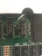
Can you please post a photo of the wire that you soldered across IC23 please.
Mark
“There are four lights!”
Step up to red alert. Sir, are you absolutely sure? It does mean changing the bulb
Looking forward to summer later in the year.
-
Ast A. Moore
- Rick Dangerous
- Posts: 2641
- Joined: Mon Nov 13, 2017 3:16 pm
Re: Blank screen issue...
No, you can’t rule out upper RAM completely. Then again, since the screen is part of the lower RAM, and it looks like the screen isn’t corrupted, it might not be lower RAM either. I just suggest a method of eliminating potential causes one by one. Technically (albeit, very unlikely) the problem might be with the ROM itself, or, possibly one of the address or data lines.
There’s no easy way of testing ICs outside a circuit, and each IC would require a special test rig in most cases. Sometimes, it’s advantageous to have a spare test “known-good” board with all ICs socketed. Then you can take individual ICs out of the board you’re woking on and putting them in the test board. Conversely, you can take out ICs from the “known-good” board and use them in the board under investigation, thus ruling out chips one by one.
That just covers the ICs. The fault may be with some of the passives (capacitors may affect timing), but diagnosing it would definitely require an oscilloscope.
Every man should plant a tree, build a house, and write a ZX Spectrum game.
Author of A Yankee in Iraq, a 50 fps shoot-’em-up—the first game to utilize the floating bus on the +2A/+3,
and zasm Z80 Assembler syntax highlighter.
Author of A Yankee in Iraq, a 50 fps shoot-’em-up—the first game to utilize the floating bus on the +2A/+3,
and zasm Z80 Assembler syntax highlighter.
-
Ast A. Moore
- Rick Dangerous
- Posts: 2641
- Joined: Mon Nov 13, 2017 3:16 pm
Re: Blank screen issue...
Bah. Tell me about it! We need to coordinate better.
Every man should plant a tree, build a house, and write a ZX Spectrum game.
Author of A Yankee in Iraq, a 50 fps shoot-’em-up—the first game to utilize the floating bus on the +2A/+3,
and zasm Z80 Assembler syntax highlighter.
Author of A Yankee in Iraq, a 50 fps shoot-’em-up—the first game to utilize the floating bus on the +2A/+3,
and zasm Z80 Assembler syntax highlighter.
Re: Blank screen issue...
Hi,
Here is the image of IC23 and a wire from pin 5 to 14 as mentioned. Sorry it’s not a great image, I cracked the glass on my camera lens...
So when I powered on this morning, no red lines. Turned off and plugged in again and got red verticle lines. I dont think it knows what is going on!
Thanks
RPS
Here is the image of IC23 and a wire from pin 5 to 14 as mentioned. Sorry it’s not a great image, I cracked the glass on my camera lens...
So when I powered on this morning, no red lines. Turned off and plugged in again and got red verticle lines. I dont think it knows what is going on!
Thanks
RPS