The latest ZXDB update will be applied this evening at 1800 BST. The update takes around 30 minutes, and the site goes down whilst this happens.

'EAR' Input Jack Mod for ZX Spectrum +2 (Grey)

For experts to discuss very technical stuff and newbies to ask why the Spectrum they bought off ebay doesn't work.
Post Reply
User avatar
Flatulentia
Drutt
Posts: 33
Joined: Wed Jun 21, 2023 10:24 pm
Location: Cambridgeshire, UK

'EAR' Input Jack Mod for ZX Spectrum +2 (Grey)

Post by Flatulentia »

If you've ever had your grey +2 apart to service the Datacorder, you may have noticed that one quarter of the quad opamp isn't used. We can use this to our advantage, especially as none of the relevant pins are connected to anything, so we don't even have to cut any tracks to make use of it.

This piqued my interest as I wanted to add an external 'EAR' socket to my +2 with the minimum of additional internal clutter and wiring. The schematic below is the solution I came up with.

Image
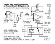
(Schematic created in KiCad)

Note: The LA6324 quad opamp on the Datacorder PCB is designated as IC302 on the official schematic, so I've kept that designation for the sake of clarity.


The intent was to provide a filtered input with enough gain to load software from a typical smartphone's headphone output. It also works well with a vintage 'shoebox' cassette recorder I refurbished recently, and from the adjustable headphone output on my Teac hi-fi cassette deck.

The opamp and its associated components form a simple bandpass filter that attenuates signals below 150Hz and above 4.5kHz. This provides a degree of simple signal conditioning by reducing any mains hum, rumble and hiss that may be present on old data cassette recordings.

A suitable bias voltage for the opamp's non-inverting input is picked up from pin 5 of the LA6324 which already connects to a potential divider that provides a voltage of around 1.75V. This is the centre point of the maximum output voltage swing of 3.5V, so the amplifier clips symmetrically.

A DC path to ground is provided for the source amplifier via the 12K resistor. This also helps maintain the circuit's input impedance somewhere in the range of 9.5K to 12K across the entire audio spectrum, thus providing a relatively simple load for any source to drive.

As we don't want to add any more noise than necessary to the Spectrum's audio output signal when not loading, the input jack is of the switched type and wired to short the input of the amplifier to ground when no jack plug is inserted.

The relay switches between the original Datacorder output from pin 7 of the LA6324 and the output of our new input amplifier (pin 8) depending upon whether the Datacorder's motor is running. The motor doesn't run when the cassette mechanism is in STOP mode, so the new amplifier becomes our input source under this condition.

A 100nF capacitor is placed across the supply pins of the LA6324 to filter out any high frequency interference that may be present on the 5V rail.

And here are the main components in-situ. Excuse the mess, but this photo was taken during the prototyping phase.

Image


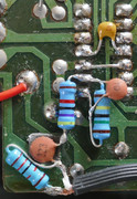
The screened cable you can see at the bottom of the photo leads out to the 3.5mm mono switched jack socket mounted on the back of the upper case directly behind the Datacorder for easy access. Mounting the jack socket in the upper half of the case means that both case halves still separate as per usual for easy servicing.

If you've already carried out a relay mod to disconnect the noisy Datacorder signal when in STOP mode and the relay is a changeover type (ie, SPDT), you're already part way there in terms of implementing this mod.

Have fun! :)
"Gandalf the Grey" Sinclair ZX Spectrum 128 +2 running "Toastrack" ROM with 'EAR' Input Jack Mod.
User avatar
Ast A. Moore
Rick Dangerous
Posts: 2643
Joined: Mon Nov 13, 2017 3:16 pm

Re: 'EAR' Input Jack Mod for ZX Spectrum +2 (Grey)

Post by Ast A. Moore »

Flatulentia wrote: Wed Jul 26, 2023 8:57 pm The opamp and its associated components form a simple bandpass filter that attenuates signals below 150Hz and above 4.5kHz.
4.5 kHz, isn’t it a tad low? Some turbo loaders go way past that cutoff frequency.
Every man should plant a tree, build a house, and write a ZX Spectrum game.

Author of A Yankee in Iraq, a 50 fps shoot-’em-up—the first game to utilize the floating bus on the +2A/+3,
and zasm Z80 Assembler syntax highlighter.
User avatar
Flatulentia
Drutt
Posts: 33
Joined: Wed Jun 21, 2023 10:24 pm
Location: Cambridgeshire, UK

Re: 'EAR' Input Jack Mod for ZX Spectrum +2 (Grey)

Post by Flatulentia »

I don't know. It's only a gentle 6dB/octave slope and beats the ancient "shoebox" cassette recorder I have that always used to manage speedload content just fine, although I don't have any to test it with at present.

If you can find a source you think it might struggle with in .WAV or .MP3 format, post a link and I'll test it out.
"Gandalf the Grey" Sinclair ZX Spectrum 128 +2 running "Toastrack" ROM with 'EAR' Input Jack Mod.
User avatar
Flatulentia
Drutt
Posts: 33
Joined: Wed Jun 21, 2023 10:24 pm
Location: Cambridgeshire, UK

Re: 'EAR' Input Jack Mod for ZX Spectrum +2 (Grey)

Post by Flatulentia »

Update time...

I've just created an 11025bps turboload file of one of my favourite Speccy games with OTLA and it loads fine from my smartphone via the input circuit as described above. ;)
"Gandalf the Grey" Sinclair ZX Spectrum 128 +2 running "Toastrack" ROM with 'EAR' Input Jack Mod.
User avatar
Ast A. Moore
Rick Dangerous
Posts: 2643
Joined: Mon Nov 13, 2017 3:16 pm

Re: 'EAR' Input Jack Mod for ZX Spectrum +2 (Grey)

Post by Ast A. Moore »

Flatulentia wrote: Thu Jul 27, 2023 1:31 am Update time...

I've just created an 11025bps turboload file of one of my favourite Speccy games with OTLA and it loads fine from my smartphone via the input circuit as described above. ;)
Neat. That’s a good test.
Every man should plant a tree, build a house, and write a ZX Spectrum game.

Author of A Yankee in Iraq, a 50 fps shoot-’em-up—the first game to utilize the floating bus on the +2A/+3,
and zasm Z80 Assembler syntax highlighter.
User avatar
1024MAK
Bugaboo
Posts: 3146
Joined: Wed Nov 15, 2017 2:52 pm
Location: Sunny Somerset in the U.K. in Europe

Re: 'EAR' Input Jack Mod for ZX Spectrum +2 (Grey)

Post by 1024MAK »

For standard audio cassettes using ‘normal’ tape, the audio bandwidth is around 10kHz to 12kHz.

Mark
:!: Standby alert :!:
“There are four lights!”
Step up to red alert. Sir, are you absolutely sure? It does mean changing the bulb :dance
Looking forward to summer later in the year.
Mad Fritz
Dizzy
Posts: 59
Joined: Wed Jun 27, 2018 1:21 pm

Re: 'EAR' Input Jack Mod for ZX Spectrum +2 (Grey)

Post by Mad Fritz »

No, but I know just did a mistype.
Waldroid
Microbot
Posts: 120
Joined: Tue May 30, 2023 6:52 pm

Re: 'EAR' Input Jack Mod for ZX Spectrum +2 (Grey)

Post by Waldroid »

Flatulentia wrote: Thu Jul 27, 2023 1:31 am Update time...

I've just created an 11025bps turboload file of one of my favourite Speccy games with OTLA and it loads fine from my smartphone via the input circuit as described above. ;)
Holy cow! How have I never heard of OTLA before? :shock:

User avatar
Flatulentia
Drutt
Posts: 33
Joined: Wed Jun 21, 2023 10:24 pm
Location: Cambridgeshire, UK

Re: 'EAR' Input Jack Mod for ZX Spectrum +2 (Grey)

Post by Flatulentia »

1024MAK wrote: Sun Jul 30, 2023 12:43 pm For standard audio cassettes using ‘normal’ tape, the audio bandwidth is around 10kHz to 12kHz.
It's far higher than that with high-end cassette decks, particularly with 3-head designs. The Teac I mentioned in my opening post is a blueprinted and calibrated V-1050 and is flat within 1dB from 18Hz to 21kHz with a TDK FE 'normal' tape. Dolby HX Pro helps a great deal in this regard, as does Dolby C to a lesser extent. Many other high-end decks can manage this, or at least close to it, if they've been accurately calibrated.

At the opposite end of the spectrum (pun intended), ye olde worlde 'shoebox' cassette recorders could often only manage 300Hz to 6kHz within 6dB. The standard tones a Spectrum produces are only 807Hz and 1614Hz, so even an analogue telephone had twice the bandwidth required for that.

The circuit above has a gentle first roll-off point at around 4.5kHz, and a second steeper roll-off point determined by the GBW product of the LA6324. They were bottom-of-the-barrel opamps with a unity gain bandwidth of only 700kHz when running from a 10V supply, so a gain of 32 brings that down to around 22kHz, actually a little less than that on a 5V supply.

The 11025bps OTLA audio file I generated uses tones of around 8kHz and 16kHz, so that just squeezes in with a few kHz to spare.

Omitting the 10pF capacitor would mean that the gain of the amplifier stage leans entirely on the opamp's own rather narrow bandwidth limit leading to high levels of distortion at high audio frequencies where the opamp has very little surplus loop gain to work as negative feedback. Large voltage swings at high frequencies were always a shortcoming of the 324 family of opamps and one of the main reasons for them not being recommended for audio circuits.

A better solution would be to either spread the gain over two opamp stages (which we can't), or to replace the LA6324 with a better quad opamp which is difficult considering the single-rail 5V supply and sensing-to-ground requirements as we don't want to interfere with the operation of the other 3 opamp stages.

I think this circuit is probably the best compromise under the circumstances.
"Gandalf the Grey" Sinclair ZX Spectrum 128 +2 running "Toastrack" ROM with 'EAR' Input Jack Mod.
User avatar
1024MAK
Bugaboo
Posts: 3146
Joined: Wed Nov 15, 2017 2:52 pm
Location: Sunny Somerset in the U.K. in Europe

Re: 'EAR' Input Jack Mod for ZX Spectrum +2 (Grey)

Post by 1024MAK »

Flatulentia wrote: Sun Jul 30, 2023 6:53 pm I think this circuit is probably the best compromise under the circumstances.
I wasn’t criticising you or the circuit design…
In fact I hit the like/love button as soon as I read your original post, not long after you posted it.

If you think my post was criticism, then I’m sorry.

I was just stating the bandwidth of a typical tape deck that uses ‘normal’ type tapes to put things into context. Not a bargain basement or high quality type (as ultimately, there are far too many variables to state the bandwidth with certainty even for new equipment, let alone something that was made long ago).

And yes, when loading or saving from a Speccy, even with a fast or turbo loader, the roll off starting at 4.5kHz is absolutely fine.

The other aspect is that the machine itself uses the edges of the pulses not the actual frequency. Why? See this topic

But as you have tested it under worse case loading speed conditions by using a fast/turbo loader, the technical details although interesting to some, are kind of outweighed by the results of your practical testing.

Mark
:!: Standby alert :!:
“There are four lights!”
Step up to red alert. Sir, are you absolutely sure? It does mean changing the bulb :dance
Looking forward to summer later in the year.
User avatar
Flatulentia
Drutt
Posts: 33
Joined: Wed Jun 21, 2023 10:24 pm
Location: Cambridgeshire, UK

Re: 'EAR' Input Jack Mod for ZX Spectrum +2 (Grey)

Post by Flatulentia »

1024MAK wrote: Sun Jul 30, 2023 7:36 pm I wasn’t criticising you or the circuit design…
In fact I hit the like/love button as soon as I read your original post, not long after you posted it.

If you think my post was criticism, then I’m sorry.
I didn't take it that way at all, Mark. No offence taken whatsoever.

I was just replying to a bandwidth related reply as a means of fleshing out the details with reasoning as to why I'd done things the way I had as I'm no longer able to edit the original post.

Apologies if it looked as though I was giving you a lecture. That was never my intent.

Yes, it's all about the edges really. As long as the amplifier can swing its output fast enough and cleanly enough to keep the timing of the edges reasonably accurate then the magic going on inside the ULA takes care of the rest. :)
"Gandalf the Grey" Sinclair ZX Spectrum 128 +2 running "Toastrack" ROM with 'EAR' Input Jack Mod.
Post Reply