Does the Nebula appear to fit into the socket it's supplied with correctly?
There are different types of socket. Does the socket that came with the Nebula appear to be the same type as the one on the board?
Speccy 48k issue 3b: Red and black screen
Re: Speccy 48k issue 3b: Red and black screen
Derek Fountain, author of the ZX Spectrum C Programmer's Getting Started Guide and various open source games, hardware and other projects, including an IF1 and ZX Microdrive emulator.
-
1024MAK

- Bugaboo
- Posts: 3152
- Joined: Wed Nov 15, 2017 2:52 pm
- Location: Sunny Somerset in the U.K. in Europe
Re: Speccy 48k issue 3b: Red and black screen
There are two classes of socket, turned pin and stamped pin. The stamped pin type can be further divided into two types, the crap type with a single contact, and the much better type that has two contacts (also called double wipe).
Further, sometimes two SIL (single in line) contact strips are sometimes used instead of a DIL socket.
Maybe you should take a photo of the socket…
Mark
PS some were also available as wire-wrap types, but that just means they had long square type pins rather than PCB pins. Unlikely these would be found on a Speecy board.
“There are four lights!”
Step up to red alert. Sir, are you absolutely sure? It does mean changing the bulb
Looking forward to summer later in the year.
-
dust hill resident

- Dizzy
- Posts: 52
- Joined: Sat Sep 23, 2023 6:05 pm
- Location: London
- Contact:
Re: Speccy 48k issue 3b: Red and black screen
I haven't tried fitting it in the socket it came in, because I worry that it wouldn't be safe to do so for various reasons (risk of damaging the pins of the socket itself, risk of being unable to remove the nebula from the socket one it's in, etc)
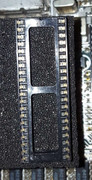
Here is a photo of the socket supplied by retroleum:
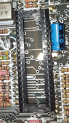
Here is a photo of the socket currently fitted in the board:
-
dust hill resident
- Dizzy
- Posts: 52
- Joined: Sat Sep 23, 2023 6:05 pm
- Location: London
- Contact:
Re: Speccy 48k issue 3b: Red and black screen
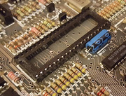
Here's another photo of the socket currently on the board because I think the first one was unclear.
-
1024MAK
- Bugaboo
- Posts: 3152
- Joined: Wed Nov 15, 2017 2:52 pm
- Location: Sunny Somerset in the U.K. in Europe
Re: Speccy 48k issue 3b: Red and black screen
The socket supplied by Retroleum is a stamped pin (double wipe) type.
The socket on the board is also a stamped pin type, but it’s no good for the type of pins used by the Nebula. Therefore, use you new snips (wire cutters) to cut the plastic of the old socket, so you can chop it into pieces. Then you can desolder each pin individually.
Then solder in the new socket.
Mark
“There are four lights!”
Step up to red alert. Sir, are you absolutely sure? It does mean changing the bulb
Looking forward to summer later in the year.
-
dust hill resident
- Dizzy
- Posts: 52
- Joined: Sat Sep 23, 2023 6:05 pm
- Location: London
- Contact:
Re: Speccy 48k issue 3b: Red and black screen
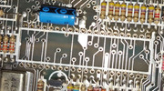
I removed the socket and finished desoldering the pins.
Unfortunately, one of the solder pads has broken off. This is presumably going to be a problem. What should I do?
photos:

Unfortunately, one of the solder pads has broken off. This is presumably going to be a problem. What should I do?
photos:
-
1024MAK
- Bugaboo
- Posts: 3152
- Joined: Wed Nov 15, 2017 2:52 pm
- Location: Sunny Somerset in the U.K. in Europe
Re: Speccy 48k issue 3b: Red and black screen
Do you mean the pad ninth from the left of the underside image you posted?
From your photo, it doesn’t appear to connect to a track on the underside, and it looks like the through-hole plating is still present. If so, the socket pin should hopefully still solder okay. Well, as long as the solder flows down the through-hole, as you won’t get the nice cone because of the missing pad.
Mark
“There are four lights!”
Step up to red alert. Sir, are you absolutely sure? It does mean changing the bulb
Looking forward to summer later in the year.
-
dust hill resident
- Dizzy
- Posts: 52
- Joined: Sat Sep 23, 2023 6:05 pm
- Location: London
- Contact:
Re: Speccy 48k issue 3b: Red and black screen
Yes, that's the one. After reading your post I decided to go ahead and solder the socket in and put the nebula in, and, it's working!!

Thank you so much for all your help!
I'm so amazed to see it working, I was so sure it'd never work again. I'm so glad and so relieved.
But now.... I'm realising, I have no idea how to put it back together, I can't for the life of me get the keyboard connectors to stay in, I tried for over half an hour and didn't manage it... what's the trick to it?
-
1024MAK
- Bugaboo
- Posts: 3152
- Joined: Wed Nov 15, 2017 2:52 pm
- Location: Sunny Somerset in the U.K. in Europe
Re: Speccy 48k issue 3b: Red and black screen
Very carefully (gradually increase the pressure, don’t jab and keep it straight) push the membrane tails in further. The spring contacts require a little bit of force to move, then once the edge of the tail has gone past the contacts, it will grip the tail.
Mark
Mark
“There are four lights!”
Step up to red alert. Sir, are you absolutely sure? It does mean changing the bulb
Looking forward to summer later in the year.
-
hellraiseruk
- Dizzy
- Posts: 70
- Joined: Thu Oct 07, 2021 6:35 pm
Re: Speccy 48k issue 3b: Red and black screen
Excellent job! I only hope you put the board in the case before you fitted the nebula, otherwise you'll have to remove it in order to put in the screw that holds the board down... ask me how I know 
Oh, and don't count your chickens just yet - yes, it's giving you a display, but could still have other issues, so some testing is in order....
JD

Oh, and don't count your chickens just yet - yes, it's giving you a display, but could still have other issues, so some testing is in order....
JD
Re: Speccy 48k issue 3b: Red and black screen
Excellent news! Really well done, and thanks for taking us through the journey. I've never seen a Nebula, and it's good to know such a thing exists and works well.
I noted in the Nebula docs, though, that they recommend ICs 3. 4. 24 and 25 are not socketed, but soldered directly to the PCB, otherwise space is limited and the keyboard will bend a bit when the machine is reassembled. You socketed your new IC3, did you not? How did that work out?
Derek Fountain, author of the ZX Spectrum C Programmer's Getting Started Guide and various open source games, hardware and other projects, including an IF1 and ZX Microdrive emulator.
Re: Speccy 48k issue 3b: Red and black screen
A couple of left over questions, in the spirit of completing the record:
Clearly Mark was right, but how did he know?dust hill resident wrote: ↑Sun Nov 05, 2023 10:02 pm Out of curiosity, I wonder, how can you tell from the readings that the ULA and IC3 are faulty?
I've never seen a Nebula, so I don't know what type of pins it has. How many "stamped pin type" of sockets are there? Google's not helping. What's the incompatibility that was identified here?
Derek Fountain, author of the ZX Spectrum C Programmer's Getting Started Guide and various open source games, hardware and other projects, including an IF1 and ZX Microdrive emulator.
-
1024MAK
- Bugaboo
- Posts: 3152
- Joined: Wed Nov 15, 2017 2:52 pm
- Location: Sunny Somerset in the U.K. in Europe
Re: Speccy 48k issue 3b: Red and black screen
Chips are made up of mainly semiconductor junctions (they also contain other “components” but are all based on what you can “make” with silicon). For clarity, I won’t go into any further details, other than to say, chip outputs (here IC3 pin 4), and chips that have open collector or three state (tri-state) outputs (ULA) or high impedance inputs (4116 DRAM) don’t have resistors internally connected to their pins.dust hill resident wrote: ↑Sun Nov 05, 2023 10:02 pm Out of curiosity, I wonder, how can you tell from the readings that the ULA and IC3 are faulty? It's interesting for me to take note and learn from it.
At the low voltage from the multimeter on the resistance ranges used (20kΩ or higher), there should be no practical conductivity, as semiconductor junctions need a minimum voltage in order to conduct. Hence the multimeter normally indicates over-range (or infinity as far as it is concerned on that particular range) or indicates a very high resistance (greater than 100kΩ).
However, often if the semiconductor material inside the chip has been damaged, it no longer forms a normal semiconductor junction, but becomes electrically leaky (the analogy could be a leaking washer in a water valve). Sometimes the semiconductor is so badly damaged that it effectively becomes a low value resistor (the analogy could be a completely perished washer in a water valve) that excessively loads the circuit.
Because some of the results indicated a resistance that was a lot lower than the normal resistance that I expected, it was a process of elimination. With a bias for suspecting the cheapest of the suspected chips (hence cutting the pin of IC3 first).
Don’t beat yourself up too much, it’s perfectly possible that this fault already existed, it had just not degraded to the point of showing any symptoms yet.dust hill resident wrote: ↑Sun Nov 05, 2023 10:02 pmIt's really sad, too. The system was all working until I fitted those last three capacitors. I wonder what happened... my best guess is that I broke the ULA or IC3 with electrostatic discharge, even though I was taking some care to prevent that.. I will be extra careful in future. I'm really sorry for the damage I've caused.
Some chips eventually fail regardless even if the equipment is used normally. Sometimes this is due to the semiconductor not being as good as it should be at time of manufacture, but working fine until eventually the degradation affects the operation.
I can’t rule out static discharge, but the ULA and the 74LSxxx series chips use bipolar technology and the feature size of the “components” on the semiconductor substrate is relatively large compared to more modern, higher density chips. As such, they are more forgiving with regards to static electricity. They are not immune, but when mounted “in circuit” on a board, the risk is relatively low, but I am assuming you live in rainy Britain and don’t wear 100% man made fibre clothing…
Stamped pin sockets are designed for the legs/pins of a chip. A Nebula is a module made up of a thin PCB with various components mounted on it. So that it can be plugged in or directly soldered in place of a original ULA, it has pin headers. These are round in profile if you look at them end-on. Unlike chip pins/legs, which have a rectangle profile, being flatter but wider if you see what I mean.
The modern stamped pin type sockets happen to work fine with the pin headers. But some of the stamped pin type sockets used in the past had relatively small openings, and won’t accept the pins of the pin headers. If you try to force a Nebula (or any other module that used pin headers) into one of these sockets, the Nebula/module will be damaged.
The other point that needs pointing out, is that after a stamped pin socket has had a module that uses pin headers in it, the contacts may become slightly bent, and the pins of a normal chip may no longer make good contact with the socket contacts.
Really, pin header PCB mounted sockets should be used, but most types are too high/tall.
Yes, do check the height/clearance between the Nebula and IC3.
Mark
“There are four lights!”
Step up to red alert. Sir, are you absolutely sure? It does mean changing the bulb
Looking forward to summer later in the year.
Re: Speccy 48k issue 3b: Red and black screen
Thank you once more @1024MAK for another wonderfully informative post. 
Derek Fountain, author of the ZX Spectrum C Programmer's Getting Started Guide and various open source games, hardware and other projects, including an IF1 and ZX Microdrive emulator.
-
dust hill resident
- Dizzy
- Posts: 52
- Joined: Sat Sep 23, 2023 6:05 pm
- Location: London
- Contact:
Re: Speccy 48k issue 3b: Red and black screen
Thank you as well! And thank you also Mark, your knowledge and guidance saved the day, and thank you too everyone who replied and encouraged me through this.
This puts things into perspective for me, it's reassuring to think it might not be my fault. My clothing is mostly cotton from what I can see on the labels, and I do live in the UK and not somewhere super dry. I make an effort to touch grounded metal objects every couple of minutes while working, and I have gloves and a wrist band, though on the day the problem started I wasn't wearing those. Ever since then I've always used them when working or touching the board.Don’t beat yourself up too much, it’s perfectly possible that this fault already existed, it had just not degraded to the point of showing any symptoms yet.
Some chips eventually fail regardless even if the equipment is used normally. Sometimes this is due to the semiconductor not being as good as it should be at time of manufacture, but working fine until eventually the degradation affects the operation.
I can’t rule out static discharge, but the ULA and the 74LSxxx series chips use bipolar technology and the feature size of the “components” on the semiconductor substrate is relatively large compared to more modern, higher density chips. As such, they are more forgiving with regards to static electricity. They are not immune, but when mounted “in circuit” on a board, the risk is relatively low, but I am assuming you live in rainy Britain and don’t wear 100% man made fibre clothing…
I appreciate the info too, because it's been on my mind all the time since the problem began, wondering what could have caused it to break. As well as being sad and frustrating at the time, it's also just a really fascinating mystery to solve.
Thank you! Luckily I noticed that just before I socketed the Nebula, and I got the board screwed in first. But I did almost make the same mistake!hellraiseruk wrote: ↑Thu Nov 09, 2023 7:36 am Excellent job! I only hope you put the board in the case before you fitted the nebula, otherwise you'll have to remove it in order to put in the screw that holds the board down... ask me how I know
Oh, and don't count your chickens just yet - yes, it's giving you a display, but could still have other issues, so some testing is in order....
JD
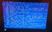
You're right too, I still need to test it with Retroleum DiagROM, but for now it's been running BASIC perfectly so far:

Sorry, I forgot to take a photo before I put the case back on... but luckily, it seemed as though on my particular model of spectrum, the nebula doesn't cover the area where IC3 is located, and the case went back on alright.dfzx wrote: ↑Thu Nov 09, 2023 9:37 am I noted in the Nebula docs, though, that they recommend ICs 3. 4. 24 and 25 are not socketed, but soldered directly to the PCB, otherwise space is limited and the keyboard will bend a bit when the machine is reassembled. You socketed your new IC3, did you not? How did that work out?
-
dust hill resident
- Dizzy
- Posts: 52
- Joined: Sat Sep 23, 2023 6:05 pm
- Location: London
- Contact:
Re: Speccy 48k issue 3b: Red and black screen
One last quick question, what kind of power supply does the spectrum use? I wonder, is it tip negative or tip positive, and what rating of amps, and what voltage does it need? The plug on my Sinclair power brick feels loose and rattles a bit, and generally feels dodgy, so I think it'd be best to replace it with a new modern supply.
Is there a particular brand of power supply you'd recommend?
Is there a particular brand of power supply you'd recommend?
-
1024MAK
- Bugaboo
- Posts: 3152
- Joined: Wed Nov 15, 2017 2:52 pm
- Location: Sunny Somerset in the U.K. in Europe
Re: Speccy 48k issue 3b: Red and black screen
Sirens sound!
Don’t mention the power or polarity!
Oh! Too late, they have

As they say on that show with Mulder and Scully, the answers out there!
So let’s start with the simple bit. Replacement connectors are available.
The polarity is also simple. The positive (+) is on the outside of the 2.1mm/5.5mm “barrel” connector. The inner part is the negative (-). This is opposite to that on most modern equipment.
The original Sinclair UK1400 PSU is an unregulated nominal 9V type rated at 1.4A.
You can either get something similar, or buy a (modern) regulated type. Modern types are normally switch mode power supply units (SMPSU).
The ZX Spectrum is not too fussy, but it depends on which issue board is fitted. All of them (16K/48K/+) should be happy with a regulated PSU that has an output of 8V to 11.8V. But it’s recommended to use one with a voltage that is less than 10V to keep the heat from the 7805 and it’s heatsink to a reasonable temperature.
The current rating should be between 1.4A and 5A.
Now the most important thing, buy from a UK company. Don’t get any cheap rubbish from the far East. This is for your own safety.
Mark
Don’t mention the power or polarity!
Oh! Too late, they have
As they say on that show with Mulder and Scully, the answers out there!
So let’s start with the simple bit. Replacement connectors are available.
The polarity is also simple. The positive (+) is on the outside of the 2.1mm/5.5mm “barrel” connector. The inner part is the negative (-). This is opposite to that on most modern equipment.
The original Sinclair UK1400 PSU is an unregulated nominal 9V type rated at 1.4A.
You can either get something similar, or buy a (modern) regulated type. Modern types are normally switch mode power supply units (SMPSU).
The ZX Spectrum is not too fussy, but it depends on which issue board is fitted. All of them (16K/48K/+) should be happy with a regulated PSU that has an output of 8V to 11.8V. But it’s recommended to use one with a voltage that is less than 10V to keep the heat from the 7805 and it’s heatsink to a reasonable temperature.
The current rating should be between 1.4A and 5A.
Now the most important thing, buy from a UK company. Don’t get any cheap rubbish from the far East. This is for your own safety.
Mark
“There are four lights!”
Step up to red alert. Sir, are you absolutely sure? It does mean changing the bulb
Looking forward to summer later in the year.
-
dust hill resident
- Dizzy
- Posts: 52
- Joined: Sat Sep 23, 2023 6:05 pm
- Location: London
- Contact:
Re: Speccy 48k issue 3b: Red and black screen
This is something I worry about a lot, it seems to me that a lot of UK sellers are just reselling imported cheap stuff. How can I be sure I'm getting something good? Are there any particular companies I should buy from, or even better, are there any specific power supplies I could buy?Now the most important thing, buy from a UK company. Don’t get any cheap rubbish from the far East. This is for your own safety.
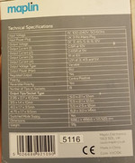
I happen to have this Maplin universal power supply, I wondered if it might work, but I notice the current it supplies at 9v is only 0.65A, much less than the 1.4A you mentioned.
Though I wonder... on my Spectrum, I replaced the 7805 with the Murata voltage regulator, if I understand right that means it's a bit more energy efficient, so perhaps the energy requirement has dropped enough that this Maplins power supply would work?
Is it safe to try it with the Maplins power supply, as long as I'm careful to get the tip and ring polarity correct? Or would this likely damage the Spectrum?
That leads me to another question, I know it's generally dangerous and likely to cause damage if you use a supply with an output voltage higher than specified for a given piece of equipment, but I don't know if it's the same story for current. I also don't know if it's dangerous to supply a voltage that's lower than specified.
-
dust hill resident
- Dizzy
- Posts: 52
- Joined: Sat Sep 23, 2023 6:05 pm
- Location: London
- Contact:
Re: Speccy 48k issue 3b: Red and black screen
I was thinking of buying this: https://www.ebay.co.uk/itm/394982944888
But it looks very generic, I can imagine it being a super cheap import kind of thing...
But it looks very generic, I can imagine it being a super cheap import kind of thing...
Re: Speccy 48k issue 3b: Red and black screen
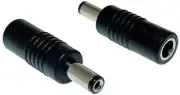
FWIW, I bought "Polarity Change Connector" (TGR-4535, CPC) and I just keep it plugged into my speccy's. Now I can simply plug any PSU I have (with suitable voltage, of course) and never worry about frying the speccy (again). Yes, the ones I have all are now-regular-centre-positive.
-
1024MAK
- Bugaboo
- Posts: 3152
- Joined: Wed Nov 15, 2017 2:52 pm
- Location: Sunny Somerset in the U.K. in Europe
Re: Speccy 48k issue 3b: Red and black screen
Yes, that would work, as long as you don’t use any power hungry expansions. The 1.4A is to allow power for expansions, such as microdrives, the ZX Printer etc.dust hill resident wrote: ↑Thu Nov 09, 2023 6:35 pm I happen to have this Maplin universal power supply, I wondered if it might work, but I notice the current it supplies at 9v is only 0.65A, much less than the 1.4A you mentioned.
Though I wonder... on my Spectrum, I replaced the 7805 with the Murata voltage regulator, if I understand right that means it's a bit more energy efficient, so perhaps the energy requirement has dropped enough that this Maplins power supply would work?
Is it safe to try it with the Maplins power supply, as long as I'm careful to get the tip and ring polarity correct? Or would this likely damage the Spectrum?
You must not use a PSU that outputs more voltage than the item of equipment can cope with. A lower than required voltage just results in malfunction.dust hill resident wrote: ↑Thu Nov 09, 2023 6:35 pm That leads me to another question, I know it's generally dangerous and likely to cause damage if you use a supply with an output voltage higher than specified for a given piece of equipment, but I don't know if it's the same story for current. I also don't know if it's dangerous to supply a voltage that's lower than specified.
The PSU must be able to supply the current that the item wants. Otherwise, it may malfunction. A PSU with a higher current capacity is fine, as long as it’s not excessive. By excessive, I mean enough current to cause damage if there is a short circuit. I gave an arbitrary figure of 5A because some modern SMPSUs can supply 4A or thereabouts.
Mark
“There are four lights!”
Step up to red alert. Sir, are you absolutely sure? It does mean changing the bulb
Looking forward to summer later in the year.
-
1024MAK
- Bugaboo
- Posts: 3152
- Joined: Wed Nov 15, 2017 2:52 pm
- Location: Sunny Somerset in the U.K. in Europe
Re: Speccy 48k issue 3b: Red and black screen
Pro-Elec is a CPC brand. CPC being part of Farnell. So assuming it’s actually a honest seller, it should be okay.dust hill resident wrote: ↑Thu Nov 09, 2023 6:46 pm I was thinking of buying this: https://www.ebay.co.uk/itm/394982944888
But it looks very generic, I can imagine it being a super cheap import kind of thing...
Here’s the CPC listing . But note, as supplied by CPC, it has the wrong barrel connector and it’s the incorrect polarity. Some traders buy these and fit a different connector.
Mark
“There are four lights!”
Step up to red alert. Sir, are you absolutely sure? It does mean changing the bulb
Looking forward to summer later in the year.

Re: Speccy 48k issue 3b: Red and black screen
Voltage has to be correct.
If a PSU isn't able to supply enough Amps it will overheat and probably shut off due to this. The device it's supplying will probably stutter and reset before this though.
Max Amps is to stop the device melting/igniting if something goes wrong with it's circuitry.
If a PSU isn't able to supply enough Amps it will overheat and probably shut off due to this. The device it's supplying will probably stutter and reset before this though.
Max Amps is to stop the device melting/igniting if something goes wrong with it's circuitry.