Gosh darn it, I’ve just put it back together, but I will check. Forgot to include the Capacitor values. Ceramics are 47nF @ 10V, Electrolytic's are 10uF @ 16V.Kiwi wrote: ↑Sun Jan 28, 2024 2:53 pm Hi, that's great - thanks again for the info and pics.
It looks like the NAND gate is simply used as a buffer for the CPU clock signal and the rest of the inputs are pulled up via the 2K2 resistor. The adjacent cap now looks like a decoupling cap.
Would you mind checking if pins 1 and 12 are connected on the LS93 ? And where the ADC clock i/p (pin 10) connects to on the LS93 ? It's probably pin 8 or 9 on the LS93. This should complete the clock gen cct.
I think all the ceramic caps are 47nf but would also mind checking and letting me know the values of the electrolytics ?
DCP Interspec BUS Expansion Adaptor
Re: DCP Interspec BUS Expansion Adaptor
There are only 10 types of people in the world – those who understand binary, and those who don’t. 
-
1024MAK

- Bugaboo
- Posts: 3171
- Joined: Wed Nov 15, 2017 2:52 pm
- Location: Sunny Somerset in the U.K. in Europe
Re: DCP Interspec BUS Expansion Adaptor
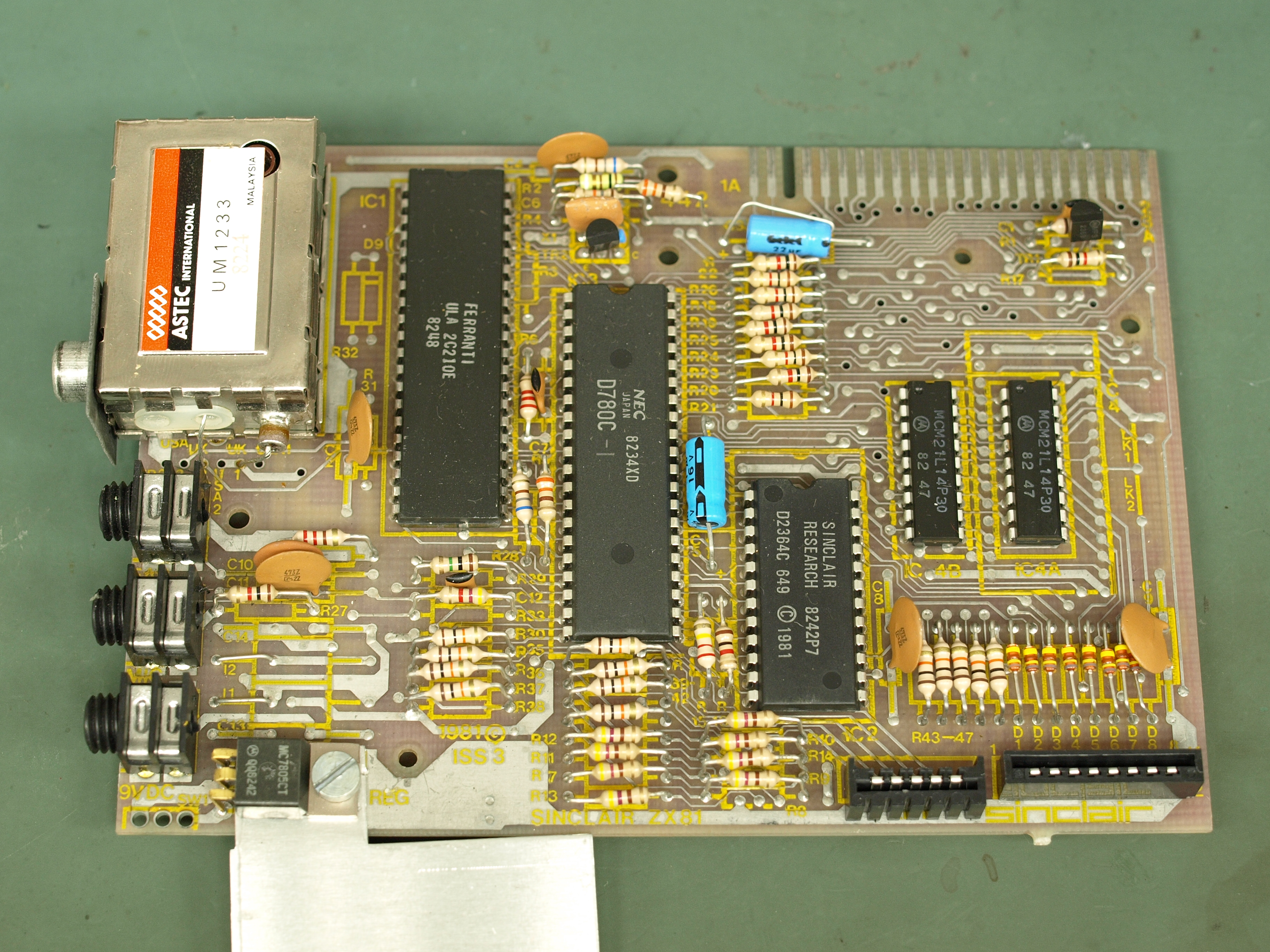
If the diodes have the same colour bands (yellow, brown, yellow, grey) as the diodes on the bottom right on this ZX81 board, then they are 1N4148 diodes.
Mark
Mark
“There are four lights!”
Step up to red alert. Sir, are you absolutely sure? It does mean changing the bulb
Looking forward to summer being good this year.
Re: DCP Interspec BUS Expansion Adaptor
Yes, thanks. I didn't notice the grey band before, double checked and they are the same1024MAK wrote: ↑Sun Jan 28, 2024 6:02 pm If the diodes have the same colour bands (yellow, brown, yellow, grey) as the diodes on the bottom right on this ZX81 board, then they are 1N4148 diodes.
Mark
There are only 10 types of people in the world – those who understand binary, and those who don’t.
Re: DCP Interspec BUS Expansion Adaptor
Pin 1 of the LS 93 is connected to pin 12 and then they read 120R to the 0V but only in the positive direction (+ to pin 1), so there must be a diode effect there within the IC. Cannot find any other connection to these pins.Kiwi wrote: ↑Sun Jan 28, 2024 2:53 pm Hi, that's great - thanks again for the info and pics.
It looks like the NAND gate is simply used as a buffer for the CPU clock signal and the rest of the inputs are pulled up via the 2K2 resistor. The adjacent cap now looks like a decoupling cap.
Would you mind checking if pins 1 and 12 are connected on the LS93 ? And where the ADC clock i/p (pin 10) connects to on the LS93 ? It's probably pin 8 or 9 on the LS93. This should complete the clock gen cct.
I think all the ceramic caps are 47nf but would also mind checking and letting me know the values of the electrolytics ?
Pin 10 on the LS93 connects to pin 7 on both LS02s.
I won't box it back up yet in case you need more info.
There are only 10 types of people in the world – those who understand binary, and those who don’t.
Re: DCP Interspec BUS Expansion Adaptor
Thanks ! One final thing,where does Pin 10 of the ADC0809 connect to on the LS93 ? I think it's probably pin 8 or 9 on the LS93 but could also be pins 11, 12, 14 or 1.
Re: DCP Interspec BUS Expansion Adaptor
Pin 10 of the ADC goes only to Pin 9 of the LS93.
There are only 10 types of people in the world – those who understand binary, and those who don’t.
Re: DCP Interspec BUS Expansion Adaptor
Thanks for checking that 
I think that finishes what I can do from the photos and without having the actual hardware in front of me. I've updated the schematic and the revised version is here: https://github.com/ZXQuirkafleeg/ZX-Int ... 20v0.2.pdf
Most of it is fairly straightforward but, at some point, the address decoder cct will need to be checked. I've pulled what I can from the photos, and think it's right, but the real check will be running a meter over the original device to check the connections - and building a copy of the hardware.
Let me know if there's anything you find in the schematic that's wrong or looks odd!
-
1024MAK
- Bugaboo
- Posts: 3171
- Joined: Wed Nov 15, 2017 2:52 pm
- Location: Sunny Somerset in the U.K. in Europe
Re: DCP Interspec BUS Expansion Adaptor
The schematic looks reasonable to me.
The I/O ports as depicted in the schematic are:
Mark
The I/O ports as depicted in the schematic are:
Code: Select all
I/O    Ref  Function
address
1F      Y0  ADC
3F      Y1  4 bit switch inputs and 4 bit relay outputs
5F      Y2  8 bit input port and 8 bit output port
7F      Y3  DCP Expansion Connector
9F Y4 DCP Expansion Connector“There are four lights!”
Step up to red alert. Sir, are you absolutely sure? It does mean changing the bulb
Looking forward to summer being good this year.
Re: DCP Interspec BUS Expansion Adaptor
Thanks for checking Mark. I'll build a version of it when I get chance and see if it works as expected.