Hi all,
I have just built a zx spectrum 48k issue 3b using a new pcb, all IC's, transistors etc are working fine as I have checked them on a known working spectrum, however it doesnt seem to matter what I do the cpu clock on pin 6 is incorrect even though its coming out from the ula on pin 32 ok so the problem seems to be somewhere between pin 32 on the ula and pin 6 on the cpu, I have tested everything I can think of resistors, diodes, voltages etc and I still cant get it to boot. Has anyone any idea's. I considered bending up the cpu pin and soldering this directly to pin 32 on the ula but dont really want to damage anything without asking for advice first. Any help would be appreciated.
Thanks
Brendan
Due to unusually high levels of website traffic you will be presenting with regular Cloudflare checks for the time being.
CPU not starting
Re: CPU not starting
Don't connect the ULA directly to the CPU. That's not a good idea.
You said "cpu clock on pin 6 is incorrect". What do you mean, "incorrect"? Stuck high? Stuck low? Erratic level? Valid signal but at the wrong speed? Give us some details to work with! Also, what test equipment are you using? You must have an oscilloscope to be measuring that signal?
The CLK circuit is pretty simple. 2 resistors, 1 capacitor and a transistor. What type of transistor are you using for TR3?
Derek Fountain, author of the ZX Spectrum C Programmer's Getting Started Guide and various open source games, hardware and other projects, including an IF1 and ZX Microdrive emulator.
-
Brendan1495
- Drutt
- Posts: 13
- Joined: Mon May 13, 2024 2:51 am
Re: CPU not starting
Hi the clock signal is erratic all over the place the transistor at T3 is a ZTX313 caps and resistors are new.
Thanks
Thanks
-
1024MAK

- Bugaboo
- Posts: 3154
- Joined: Wed Nov 15, 2017 2:52 pm
- Location: Sunny Somerset in the U.K. in Europe
Re: CPU not starting
The type of transistor used in the clock circuit (TR3) is critical. If the turn off time of the transistor is too long, the voltage at the collector will stay low or the output pulse will be short and distorted.
ZTX313 have been obsolete for years and the other main substitute is also discontinued. Where did you get your ZTX313 from?
A transistor tester will not show up this problem.
The other possible cause is a poor connection. Either a dry joint or a PCB track fault.
Mark
ZTX313 have been obsolete for years and the other main substitute is also discontinued. Where did you get your ZTX313 from?
A transistor tester will not show up this problem.
The other possible cause is a poor connection. Either a dry joint or a PCB track fault.
Mark
“There are four lights!”
Step up to red alert. Sir, are you absolutely sure? It does mean changing the bulb
Looking forward to summer later in the year.
-
MustardTiger

- Microbot
- Posts: 131
- Joined: Tue May 02, 2023 8:05 pm
Re: CPU not starting
This sounds like the exact same issue I had when I built up a new 3b PCB. I never figured out the problem. There's a thread here viewtopic.php?t=9628 ignore the first few posts about voltages.
I'd be interested if you have the same problem with the CPU clock being between ~4v low and ~5v high like I was seeing
I'd be interested if you have the same problem with the CPU clock being between ~4v low and ~5v high like I was seeing
Re: CPU not starting
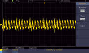
I don't suppose you can post pictures of the waveforms on the base of TR3 and on pin 32 of the ULA (ie either side of R24)? Possibly there's a short or TR3 is faulty and the signal isn't being buffered like it should be. If that's the case then it should be possible to see the base sitting at 0V or +5V rather than matching what the ULA output pin is doing.
-
1024MAK
- Bugaboo
- Posts: 3154
- Joined: Wed Nov 15, 2017 2:52 pm
- Location: Sunny Somerset in the U.K. in Europe
Re: CPU not starting
Also a 'scope waveform of the base and the collector of TR3 if you have a dual channel oscilloscope. Note that the 'scope must have a bandwidth of 25MHz or better, ideally 50MHz or better.
Mark
Mark
“There are four lights!”
Step up to red alert. Sir, are you absolutely sure? It does mean changing the bulb
Looking forward to summer later in the year.
-
Brendan1495
- Drutt
- Posts: 13
- Joined: Mon May 13, 2024 2:51 am
Re: CPU not starting
Hi, from am old board I originally had a MPS2369 but changed it was trying the process of elimination1024MAK wrote: ↑Mon May 13, 2024 10:39 am The type of transistor used in the clock circuit (TR3) is critical. If the turn off time of the transistor is too long, the voltage at the collector will stay low or the output pulse will be short and distorted.
ZTX313 have been obsolete for years and the other main substitute is also discontinued. Where did you get your ZTX313 from?
A transistor tester will not show up this problem.
The other possible cause is a poor connection. Either a dry joint or a PCB track fault.
Mark
Re: CPU not starting
You do need to tell us how you're observing the clock signal and the waveforms around the transistor. If you have an oscilloscope do you know how to capture images from it so you can upload them?
Derek Fountain, author of the ZX Spectrum C Programmer's Getting Started Guide and various open source games, hardware and other projects, including an IF1 and ZX Microdrive emulator.
-
Brendan1495
- Drutt
- Posts: 13
- Joined: Mon May 13, 2024 2:51 am
Re: CPU not starting
Not really to be honest just got it and trying to learn to use it will have a look at the manual
Re: CPU not starting
If it's not obvious from the manual if it can export screenshots, a snap with a mobile phone camera will do. Just so we can look and see how they compare to a working board. Heh - my oscilloscope is a hulking great 1980s CRT beast, so the only way to capture the waveforms is to take a photo. It's all analogue, mainly bipolar transistors with just a couple of integrated circuits (probably opamps). Nothing as sophisticated as a microprocessor 
-
Brendan1495
- Drutt
- Posts: 13
- Joined: Mon May 13, 2024 2:51 am
Re: CPU not starting
Hi All,
I managed to save the images
Base
Collector
Pin 32 ULS
R24 Left
R24 Right
Thanks
I managed to save the images
Base
Collector
Pin 32 ULS
R24 Left
R24 Right
Thanks
Re: CPU not starting
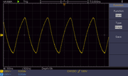
I've got a couple of traces from an issue 3 for comparison. This is from pin 32 of the ULA:

The waveform is the same as yours, which is good because it means your ULA is working. Or at least I think it does. I don't know how to read your 'scope's output. It looks like your waveform is swinging from positive to negative, which surely can't be right, can it?
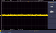
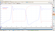
Moving on, this is the waveform on the TR3 base:

It appears C67 and R24 clip the signal to about 1.5V with a negative bias. I'm not sure quite what's going on there, other than to say that's clearly what's needed at the base of TR3 because then the clock circuit works.
So not withstanding my confusion about the voltage level of your ULA signal, it appears your ULA and the track to R24 are OK, but the signal is lost on the left side of the C67/R24 filter. So it seems that filter isn't working. It's only 2 components so you should be able to track it down. Check the traces for shorts, then replace capacitor C67?
The waveform is the same as yours, which is good because it means your ULA is working. Or at least I think it does. I don't know how to read your 'scope's output. It looks like your waveform is swinging from positive to negative, which surely can't be right, can it?
Moving on, this is the waveform on the TR3 base:
It appears C67 and R24 clip the signal to about 1.5V with a negative bias. I'm not sure quite what's going on there, other than to say that's clearly what's needed at the base of TR3 because then the clock circuit works.
So not withstanding my confusion about the voltage level of your ULA signal, it appears your ULA and the track to R24 are OK, but the signal is lost on the left side of the C67/R24 filter. So it seems that filter isn't working. It's only 2 components so you should be able to track it down. Check the traces for shorts, then replace capacitor C67?
Derek Fountain, author of the ZX Spectrum C Programmer's Getting Started Guide and various open source games, hardware and other projects, including an IF1 and ZX Microdrive emulator.
Re: CPU not starting
I agree - the signal at the base of TR3 on your trace looks odd. So if TR3 itself it OK, then it's the R24/C67 filter (which I think is intended to make the clock signal more square, at least in the high period) that's not right.
-
1024MAK
- Bugaboo
- Posts: 3154
- Joined: Wed Nov 15, 2017 2:52 pm
- Location: Sunny Somerset in the U.K. in Europe
Re: CPU not starting
ZX Spectrum Z80 clock circuit.
This is the circuit:


The reason why this circuit is used is because the ULA cannot output a rail to rail signal (meaning its output voltage is insufficient) and the clock pin (6) on the NMOS Z80 requires a input voltage much higher than a normal TTL logic signal. Hence TR3 and it’s associated components act as a level shifter.
Starting at the beginning, R73 provides a small bias voltage to improve the operation of the circuit. Sinclair added this after the issue one and issue two boards had been produced, some issue one and issue two boards were modified.
R24 limits the current into the base terminal of the transistor to prevent too much current from flowing and to operate TR3 within its normal range. C67 is not to filter the signal, but there to improve the switch off-time of the transistor.
In this configuration, TR3 inverts the signal. It also amplifies both the voltage and the current. When on (about 0.55V to 0.65V on the base) the transistor is fully switched on, and the collector voltage will be 0.2V or less.
When TR3 is fully off, the collector to emitter will be effectively open circuit. Now R25 pulls the collector voltage up to +5V (or very nearly to this voltage).
The result is that pin 6 of the Z80 sees a (imperfect) square wave between 0.2V and very nearly +5V. Hence meeting the requirements specified by Zilog.
Bipolar transistors have a much slower turn off time when used in a circuit like this. Hence the need for a fast switching transistor and the inclusion of a “speed-up capacitor” C67.
Mark
This is the circuit:
The reason why this circuit is used is because the ULA cannot output a rail to rail signal (meaning its output voltage is insufficient) and the clock pin (6) on the NMOS Z80 requires a input voltage much higher than a normal TTL logic signal. Hence TR3 and it’s associated components act as a level shifter.
Starting at the beginning, R73 provides a small bias voltage to improve the operation of the circuit. Sinclair added this after the issue one and issue two boards had been produced, some issue one and issue two boards were modified.
R24 limits the current into the base terminal of the transistor to prevent too much current from flowing and to operate TR3 within its normal range. C67 is not to filter the signal, but there to improve the switch off-time of the transistor.
In this configuration, TR3 inverts the signal. It also amplifies both the voltage and the current. When on (about 0.55V to 0.65V on the base) the transistor is fully switched on, and the collector voltage will be 0.2V or less.
When TR3 is fully off, the collector to emitter will be effectively open circuit. Now R25 pulls the collector voltage up to +5V (or very nearly to this voltage).
The result is that pin 6 of the Z80 sees a (imperfect) square wave between 0.2V and very nearly +5V. Hence meeting the requirements specified by Zilog.
Bipolar transistors have a much slower turn off time when used in a circuit like this. Hence the need for a fast switching transistor and the inclusion of a “speed-up capacitor” C67.
Mark
Last edited by 1024MAK on Tue May 14, 2024 11:43 am, edited 1 time in total.
“There are four lights!”
Step up to red alert. Sir, are you absolutely sure? It does mean changing the bulb
Looking forward to summer later in the year.
-
1024MAK
- Bugaboo
- Posts: 3154
- Joined: Wed Nov 15, 2017 2:52 pm
- Location: Sunny Somerset in the U.K. in Europe
Re: CPU not starting
I suspect that AC coupling mode is selected. For this circuit DC coupling mode should be used unless the 'scope used cannot process DC signals with a negative component.
Also the timebase needs to be adjusted, ideally the screen should be displaying one and a half to two cycles of the waveform, no more.
TR3 base voltage should be around 0.55V to 0.65V during the high part of the cycle, and around 0V during the low part of the cycle. Capacitor C67 will however cause brief negative voltage spikes. This is because it cannot charge up instantaneously. So when the ULA pin goes low, the transistor bass will go below 0V. This actually helps as it removes charge from the transistors base terminal helping it turn off quicker than it would otherwise do.
If TR3 does not turn off quickly, by the time it does turn off, the signal from the ULA will have changed state again. The result being the clock signal to the Z80 being a constant low or very short high pulses instead of a (imperfect) square wave with an appropriate duty cycle of 50/50.
Open circuit faults in the base circuit tend to result in TR3 not switching on, hence pin 6 of the Z80 stays a constant high. If R25 is open circuit or too high a value, the voltage on pin 6 will not go high enough.
The value of C67 is critical, too low and it doesn’t have the desired effect. To large and it completely messes up the operation of the circuit.
Mark
“There are four lights!”
Step up to red alert. Sir, are you absolutely sure? It does mean changing the bulb
Looking forward to summer later in the year.
-
1024MAK
- Bugaboo
- Posts: 3154
- Joined: Wed Nov 15, 2017 2:52 pm
- Location: Sunny Somerset in the U.K. in Europe
Re: CPU not starting
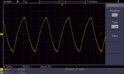
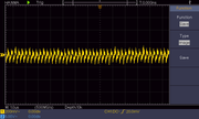
Here's some screenshots from my PicoScope of one of my ZX Spectrum boards.
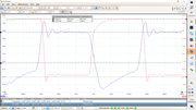
Blue waveform is TR3 base. Voltage scale is shown on the left of the screen. Set to the +/-2V range but scaled and moved to almost fill the screen.
Red waveform is TR3 collector / Z80 pin 6. Voltage scale is shown on the right of the screen. Set to the +/-10V range but scaled and moved to almost fill the screen.
As you can see, I have the timebase set to 50ns/div.
Mark
“There are four lights!”
Step up to red alert. Sir, are you absolutely sure? It does mean changing the bulb
Looking forward to summer later in the year.
-
Brendan1495
- Drutt
- Posts: 13
- Joined: Mon May 13, 2024 2:51 am
Re: CPU not starting
Hi all and thanks for your continued help, I have made some changes but to no avail
Changed C26
Changed R24 & R25
Changed TR3 to a MPS2369
Changed Voltage regulator
Still the same
I have also checked the voltages
R73 - 4.89 Right, 2.77 Left
R24 - 2.9 Right, 0.79 Left
TR3 B - 0.79, E - 0, C - 0
Pin 6 on CPU - 0
R25 - 4.88 Right, 0 Left.
Changed C26
Changed R24 & R25
Changed TR3 to a MPS2369
Changed Voltage regulator
Still the same
I have also checked the voltages
R73 - 4.89 Right, 2.77 Left
R24 - 2.9 Right, 0.79 Left
TR3 B - 0.79, E - 0, C - 0
Pin 6 on CPU - 0
R25 - 4.88 Right, 0 Left.
-
1024MAK
- Bugaboo
- Posts: 3154
- Joined: Wed Nov 15, 2017 2:52 pm
- Location: Sunny Somerset in the U.K. in Europe
Re: CPU not starting
Can you please disconnect the power, then remove the ULA (I presume all chips are in sockets). Power up again and retest the voltages that you did in your last post.
Next, power off again. Now use a test lead to connect R73 left lead to a 0V/ground point. Please ensure you have the correct lead of R73. And keep the ULA out of the socket. That is, DO NOT fit the ULA. Now power up again and do the voltage tests again (except you don't need to do the voltages for R73).
Disconnect the test lead.
Please report your test results here.
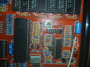
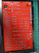
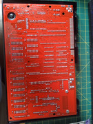
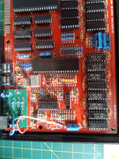
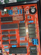
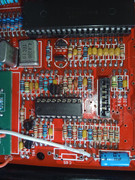
Also, can you please post a photo of the area of the board showing TR3 and the associated components (top side) and the underside.
Mark
Next, power off again. Now use a test lead to connect R73 left lead to a 0V/ground point. Please ensure you have the correct lead of R73. And keep the ULA out of the socket. That is, DO NOT fit the ULA. Now power up again and do the voltage tests again (except you don't need to do the voltages for R73).
Disconnect the test lead.
Please report your test results here.
Also, can you please post a photo of the area of the board showing TR3 and the associated components (top side) and the underside.
Mark
Last edited by 1024MAK on Tue May 14, 2024 2:59 pm, edited 1 time in total.
“There are four lights!”
Step up to red alert. Sir, are you absolutely sure? It does mean changing the bulb
Looking forward to summer later in the year.
-
Brendan1495
- Drutt
- Posts: 13
- Joined: Mon May 13, 2024 2:51 am
Re: CPU not starting
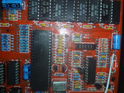
Some pictures of the board, can someone see anywhere I messed up?

-
1024MAK
- Bugaboo
- Posts: 3154
- Joined: Wed Nov 15, 2017 2:52 pm
- Location: Sunny Somerset in the U.K. in Europe
Re: CPU not starting
Nothing springs out as being wrong with the Z80 clock part of the circuitry.
Mark
Mark
“There are four lights!”
Step up to red alert. Sir, are you absolutely sure? It does mean changing the bulb
Looking forward to summer later in the year.
-
Brendan1495
- Drutt
- Posts: 13
- Joined: Mon May 13, 2024 2:51 am
Re: CPU not starting
1024MAK wrote: ↑Tue May 14, 2024 2:49 pm Can you please disconnect the power, then remove the ULA (I presume all chips are in sockets). Power up again and retest the voltages that you did in your last post.
Next, power off again. Now use a test lead to connect R73 left lead to a 0V/ground point. Please ensure you have the correct lead of R73. And keep the ULA out of the socket. That is, DO NOT fit the ULA. Now power up again and do the voltage tests again (except you don't need to do the voltages for R73).
Disconnect the test lead.
Please report your test results here.
Also, can you please post a photo of the area of the board showing TR3 and the associated components (top side) and the underside.
Mark
Will Do
-
Brendan1495
- Drutt
- Posts: 13
- Joined: Mon May 13, 2024 2:51 am
Re: CPU not starting
Hi Mark,1024MAK wrote: ↑Tue May 14, 2024 2:49 pm Can you please disconnect the power, then remove the ULA (I presume all chips are in sockets). Power up again and retest the voltages that you did in your last post.
Next, power off again. Now use a test lead to connect R73 left lead to a 0V/ground point. Please ensure you have the correct lead of R73. And keep the ULA out of the socket. That is, DO NOT fit the ULA. Now power up again and do the voltage tests again (except you don't need to do the voltages for R73).
Disconnect the test lead.
Please report your test results here.
Also, can you please post a photo of the area of the board showing TR3 and the associated components (top side) and the underside.
Mark
No ULA
R73 5.03 Right, 2.81 Left
R24 2.93 Right, 0.87 Left
Base 0.83, collector 0, Emitter 0
Pin 6 CPU 0
R25 5.03 Right, 0.83 Left
No ULA R73 Left Side connected to ground
R24 0 Right, 0 Left
Base 0, collector 5.03, Emitter 0
Pin 6 CPU - 5
R25 5.03 Right, 5.03 Left
Thanks for the help
-
1024MAK
- Bugaboo
- Posts: 3154
- Joined: Wed Nov 15, 2017 2:52 pm
- Location: Sunny Somerset in the U.K. in Europe
Re: CPU not starting
See comments in GREEN and RED
MarkBrendan1495 wrote: ↑Tue May 14, 2024 8:51 pm No ULA
R73 5.03 Right, 2.81 Left - Okay
R24 2.93 Right, 0.87 Left - I would expect R24 right to be approximately the same as R73 left
Base 0.83, collector 0, Emitter 0 - Okay
Pin 6 CPU 0 - Okay
R25 5.03 Right, 0.83 Left - R25 left should be 0V or very close to 0V
Can you please double check these results.
No ULA R73 Left Side connected to ground
R24 0 Right, 0 Left - Okay
Base 0, collector 5.03, Emitter 0 - Okay
Pin 6 CPU - 5 - Okay assuming you mean +5V
R25 5.03 Right, 5.03 Left - Okay
“There are four lights!”
Step up to red alert. Sir, are you absolutely sure? It does mean changing the bulb
Looking forward to summer later in the year.