edge connector measures

For experts to discuss very technical stuff and newbies to ask why the Spectrum they bought off ebay doesn't work.
Post Reply
ultimate
Drutt
Posts: 9
Joined: Wed Jun 17, 2020 11:49 am

edge connector measures

Post by ultimate »

Hello,

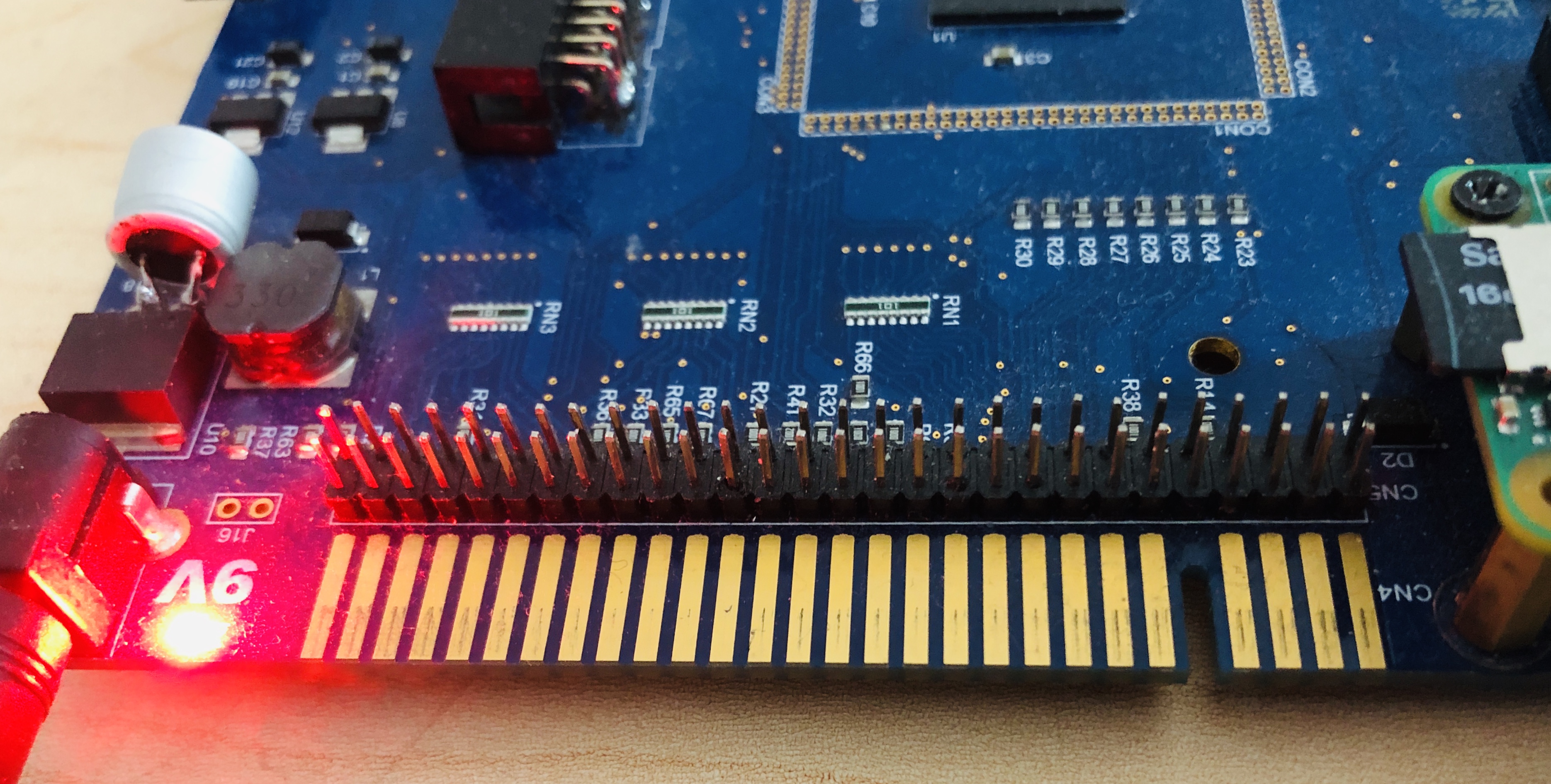
Could anybody owning a ZX spectrum 48K or plus measure the dimensions of edge board connector? I don't have one and need the info to design a pluggable pcb.

What I need is A,B and C size in milimiters (see attached image)

thank you very much.

Image
Spezzi63
Drutt
Posts: 44
Joined: Sat Dec 28, 2019 1:36 pm

Re: edge connector measures

Post by Spezzi63 »

Hi,
Your plug-in extension should have a plug with a slot key, or are you thinking of the solid bus line for other devices.
Then "C" of width, with a small margin, would be the solution.
For example: https://tinyurl.com/y8gfft85
User avatar
1024MAK
Bugaboo
Posts: 3123
Joined: Wed Nov 15, 2017 2:52 pm
Location: Sunny Somerset in the U.K. in Europe

Re: edge connector measures

Post by 1024MAK »

The pitch, ‘A’ is easy. It’s 0.1 inch, when converting to metric, make sure you use enough decimal places otherwise the accumulated error will eventually result in alignment problems.

The edge connector on a ZX Spectrum is a sub set of an electronic industry standard. So if you search for say “card edge connector standard drawing pdf” you should be able to find various documents showing details of the female connectors at the very least.

Note that as the standard was set when imperial was the favoured measurement system, all dimensions were specified in inches. The series / type you want to look at are 0.1 (2.54mm) pitch.

Some schematic capture and PCB CAD layout applications can load third party designed edge-connector symbols and their corresponding PCB layout. You will however have to search to find the symbol files and layout data.

Mark
:!: Standby alert :!:
“There are four lights!”
Step up to red alert. Sir, are you absolutely sure? It does mean changing the bulb :dance
Looking forward to summer later in the year.
ultimate
Drutt
Posts: 9
Joined: Wed Jun 17, 2020 11:49 am

Re: edge connector measures

Post by ultimate »

Thanks a lot !!

I'm looking for that card edge connector standard

@Spezzzi63, I don't fully understand what you mean with "C" of width, I want to have the schematic symbol and footprint for bus edge connector (female, like the one present in interface1 or kemptson interface) and also the schematic symbol and footprint for board edge connector (male, the one present in spectrum mainboard or PC ISA card). I want those to use in my projects, the first will be a simple bus expansor just to practice.

So, I need the measures I showed in the picture, A is the pitch (distance between center of pads), C is distance betweens pads and B is slot width. I will also need the pad width, let's call it D

Thanks to everybody for interesting replies
Spezzi63
Drutt
Posts: 44
Joined: Sat Dec 28, 2019 1:36 pm

Re: edge connector measures

Post by Spezzi63 »

ultimate wrote: Thu Jun 18, 2020 1:27 pm @Spezzzi63, I don't fully understand what you mean with "C" of width, I want to have the schematic symbol and footprint for bus edge connector (female,
Sorry, I misunderstood something ;(
User avatar
Seven.FFF
Manic Miner
Posts: 744
Joined: Sat Nov 25, 2017 10:50 pm
Location: USA

Re: edge connector measures

Post by Seven.FFF »

D = A - C
Robin Verhagen-Guest
SevenFFF / Threetwosevensixseven / colonel32
NXtel NXTP ESP Update ESP Reset CSpect Plugins
ultimate
Drutt
Posts: 9
Joined: Wed Jun 17, 2020 11:49 am

Re: edge connector measures

Post by ultimate »

Seven.FFF wrote: Thu Jun 18, 2020 7:05 pmD = A - C
right, thanks for point it out
ultimate
Drutt
Posts: 9
Joined: Wed Jun 17, 2020 11:49 am

Re: edge connector measures

Post by ultimate »

I couldn't find the card edge standard but a plethora of datasheets for vendors, and most of them provide only pitch size (A), those providing other sizes are highly dependant of connector size and number of pins, also slot size is very hard to find.

My conclusion based mainly on [1] [2] and [3] is you can selected the desired pitch, in my case A=2.54 mm and pad gap size (C) varies from 1.07 +- 0.05 mm while pad size is about 1.40-1.60 (D) which is consistent with A-C = 2.54 - 1.07 = 1.47 +- 0.05 = 1.42-1.52 , but have no info about slot size in zx spectrum mainboard, some docs suggest sizes like 0.94mm but seems too small to me, maybe is only applicable to small factor cards

[1] http://wppro.com/content/en/products/ca ... ct/119.pdf
[2] https://media.digikey.com/pdf/Data%20Sh ... ectors.pdf
[3] https://www.te.com/commerce/DocumentDel ... F5532600-5
ultimate
Drutt
Posts: 9
Joined: Wed Jun 17, 2020 11:49 am

Re: edge connector measures

Post by ultimate »

using the picture posted by Spezzi63 [1] I get the following measures:

A= 5mm
B= 3-4 mm
C=1 mm (in other pictures I checked in the net I got 2-3 mm)
D=3 mm

I don't know if this picture is real size or not, do you think these measure are accurate enough?

[1] https://tinyurl.com/y8gfft85
User avatar
Seven.FFF
Manic Miner
Posts: 744
Joined: Sat Nov 25, 2017 10:50 pm
Location: USA

Re: edge connector measures

Post by Seven.FFF »

A is always exactly 0.1 inches, as Mark said. So it cannot be 5mm.
Robin Verhagen-Guest
SevenFFF / Threetwosevensixseven / colonel32
NXtel NXTP ESP Update ESP Reset CSpect Plugins
Spezzi63
Drutt
Posts: 44
Joined: Sat Dec 28, 2019 1:36 pm

Re: edge connector measures

Post by Spezzi63 »

Maybe I measured something inaccurately.
Does it help you ?
Image
User avatar
1024MAK
Bugaboo
Posts: 3123
Joined: Wed Nov 15, 2017 2:52 pm
Location: Sunny Somerset in the U.K. in Europe

Re: edge connector measures

Post by 1024MAK »

I can do some appropriate measurements later, but as I said, the edge-connector is a sub set of the industry standard 0.1” pitch. The same pitch was/is used for ISA cards in IBM PCs and compatibles. Plus it was/is used in many industrial card rack systems.

Mark
:!: Standby alert :!:
“There are four lights!”
Step up to red alert. Sir, are you absolutely sure? It does mean changing the bulb :dance
Looking forward to summer later in the year.
ultimate
Drutt
Posts: 9
Joined: Wed Jun 17, 2020 11:49 am

Re: edge connector measures

Post by ultimate »

Spezzi63 wrote: Thu Jun 18, 2020 11:57 pm Maybe I measured something inaccurately.
Does it help you ?
Image
thanks a lot!! it really helps me!

when measuring that picture directly on screen with a rule I got sizes very diferent to those write down in the picture, so for sure it is not a real size image or maybe my screen resolution introduces a deformation in size

again thanks a lot
ultimate
Drutt
Posts: 9
Joined: Wed Jun 17, 2020 11:49 am

Re: edge connector measures

Post by ultimate »

1024MAK wrote: Fri Jun 19, 2020 12:44 am I can do some appropriate measurements later, but as I said, the edge-connector is a sub set of the industry standard 0.1” pitch. The same pitch was/is used for ISA cards in IBM PCs and compatibles. Plus it was/is used in many industrial card rack systems.
the picture sent by Spezzi63 is what I needed but I'm still interested in that edge-connector industry standard documentation, have you got any link to the official standard doc? I'm still looking for it in the net but without success until now
User avatar
1bvl109
Dizzy
Posts: 98
Joined: Tue Jun 04, 2019 9:00 pm

Re: edge connector measures

Post by 1bvl109 »

ultimate wrote: Fri Jun 19, 2020 11:45 pm ... but I'm still interested in that edge-connector industry standard documentation, have you got any link to the official standard doc?
Wikipedia on ISA simply refers to "standard edge connector sockets". So it may be a quasi-standard which is older than dirt.
"Truth would quickly cease to be stranger than fiction, once we got used to it." - H.L. Mencken
User avatar
1024MAK
Bugaboo
Posts: 3123
Joined: Wed Nov 15, 2017 2:52 pm
Location: Sunny Somerset in the U.K. in Europe

Re: edge connector measures

Post by 1024MAK »

Well ISA in comparison is still the ‘new guy on the block’ as card edge connectors were in use in the 1960s.

I don’t have a link to a particular ‘standard’, it’s likely it was introduced long ago by one manufacturer or came about as a government or military requirement and then was copied by other manufacturers and hence became a de facto standard used by the electronics industries.

This document does give some details on page 57 detailing the dimensions of the PCB tracks.

Mark
:!: Standby alert :!:
“There are four lights!”
Step up to red alert. Sir, are you absolutely sure? It does mean changing the bulb :dance
Looking forward to summer later in the year.
ultimate
Drutt
Posts: 9
Joined: Wed Jun 17, 2020 11:49 am

Re: edge connector measures

Post by ultimate »

ok, thanks for the info.

I was also searching the web to buy connectos for edge board connector, It seems it's hard do get it nowadays, ISA is out of sell everywhere, I can only find PCI and other IDC connectors that probably will fit.

Where do you buy connectors for ZX bus?

thanks!
Spezzi63
Drutt
Posts: 44
Joined: Sat Dec 28, 2019 1:36 pm

Re: edge connector measures

Post by Spezzi63 »

Hi,
at the moment I only have this contact:
http://www.divide.cz/?x=eshopn
best regards
Z80
Drutt
Posts: 9
Joined: Fri Jun 15, 2018 9:27 am

Re: edge connector measures

Post by Z80 »

Hi !

That's just a standard, widespread (at the time, at least) 1/10th of an inch Amphenol card end connector, but there's a little trick about the female version :

If you're going to just solder it to a PCB edge laying flat, you can use any model, but if you're willing to provide a bus pass-through behind your card so you don't end up unable to plug anything else, you'll want to connect it to a male extension PCB (and you'll usually fit your main card vertically so you don't have to route all the tracks all the way to the other side of your project PCB).

Then again, in order to not have to solder every pins from the female connector to your project board then again from your project board to the male extension, the easiest way is to use a female connector with pins long enough to get trhough your PCB then still reach out to the male extension in one go with enough remaining length to allow sturdy soldering.

Clearly speaking, you'll want to use wire wrap models.

Wrapping was an old way to assemble electronic composents without any solder : a special tool was used to wrap severel rounds of stripped wire around components pins to wire them.

The said componsents were usually mounted on special PCB boards that were entirely perforated every 1/10th of an inch, without any copper tracks. So everything was wired together using insulated wires on the pins side, using only two tools : a stripper and a wrapping tool.

https://en.wikipedia.org/wiki/Wire_wrap

Since the corresponding connectors and IS sockets had very long and sturdy nickel pins, they were ideal to use on the Spectrum, as they allowed to connect both the extension card and the extension output male bus connector in one go.

As I said above, you could (and still can) also find IC sockets meant for wrapping, that can also be diverted from their initial purpose to connect several PCBs stacked one above another, or to piggy-back components. Such an example of use can be found on AY or DMA extensions for the original Spectrum that plug directly in place of the Z80, which in turn gets moved up on the wrapping connector soldered to the new PCB.

You should still be able to find some, here some search suggestions :

https://www.google.com/search?q=1%2F10% ... +connector

https://www.google.com/search?q=.1%20in ... 0connector

https://www.google.com/search?q=1%2F10% ... 0connector

https://www.google.com/search?q=2.54%20 ... 0connector

The one sold at divide.cz are the standard soldering model and not the wirewrapping models, so they're not the most handy (depending on your project, of course). On the other hand, they're sold with both ends already sawed off and a plastic key across pins 5A/B, so they're ready to plug in... But that's probably not the most difficult thing to do by yourself anyway. ^^
ultimate
Drutt
Posts: 9
Joined: Wed Jun 17, 2020 11:49 am

Re: edge connector measures

Post by ultimate »

thanks for your long detailed comment.

Effectively I want to make a pass-through board, in fact an bus expansor board, but my idea is to provide an alternative socket to connect to speccy bus just because of the difficult to get a speccy edge female socket. I think this is pretty a nonsense since every speccy board I want to connect to my expansor board is expecting an edge connector exactly the same present at the spectrum but this is for my personal use.

Being schematic, my idea is something like this:

zx edge bus ----> 60 pin IDC connector or pin row ---> zx edge bus
|
'--> 16 + 8 female pin row_ (maybe more)


In order to have all the bus pinout in a more accesible socket and several signal in a pin row similar to a rpi gpio socket


when saying 60 pin idc socket I'm thinking in something like this:

https://www.alibaba.com/product-detail/ ... 3ee27jtwT1

or even like this:

https://cables24.com/es/otros/sub-d/297 ... olex-70928

or ribbon or flat wire connectors, maybe in related subsets (16 wire for memory, 8 wire for data...)

an interesting discussion would be what kind of connector is more interesting as an actual easy accessible replacement?
Last edited by ultimate on Wed Jul 08, 2020 5:46 pm, edited 1 time in total.
User avatar
Seven.FFF
Manic Miner
Posts: 744
Joined: Sat Nov 25, 2017 10:50 pm
Location: USA

Re: edge connector measures

Post by Seven.FFF »

I think twin 0.1" pin headers (either Male or female, doesn't really matter) like the Raspberry Pi GPIO socket is perfect.

My Spectrum Next has one of these too! :)

Image
Robin Verhagen-Guest
SevenFFF / Threetwosevensixseven / colonel32
NXtel NXTP ESP Update ESP Reset CSpect Plugins
Post Reply