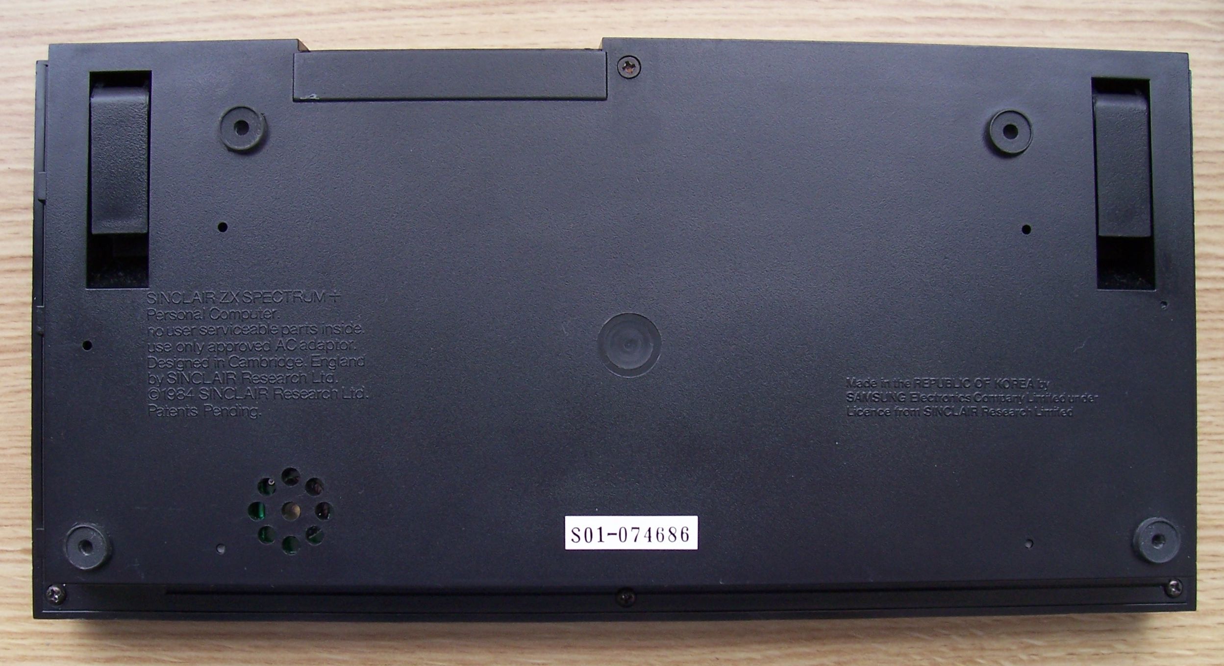
The photo is fine.
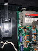
That modulator has definitely not been bypassed, so
no composite video modification has been done.
Definitely need the services of a multimeter. If your friend has a logic probe or better yet, an oscilloscope, tell him that they would be helpful as well...
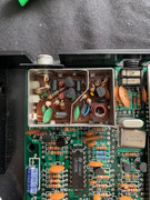
First, whatever the measurement, the negative / black meter lead / probe has to connect to a 0V/GND (ground) point (ground in this context does NOT mean mains earth, but the circuit common). Good places are the metal tab of the 7805 voltage regulator (the thing that the metal heatsink is attached to) or the case of the modulator.
Set the multimeter to the 20V (or equivalent) DC range. The computer does need to be powered up for these tests.
With the positive / red probe, carefully (don’t slip) test the following points:
- IC14 (LM1889) pins 14, 15, 16 (expected voltage is between +11V and +12V). DIL chips (as fitted to a ZX Spectrum) count anti-clockwise, see this topic for an example showing the Z80A microprocessor.
We don’t have a board layout for the issue 4S board, but it is based on the earlier issue 4A, here is the layout for the issue 4A
- Positive lead of capacitor C44 (expected voltage is +12V). This type of capacitor is an electrolytic, they have a black or white band marked with minus signs (-), the band will have arrows pointing to the negative lead of the capacitor. There may be a plus symbol marked on the PCB next to the positive (+) lead.
- Positive lead of capacitor C45 (expected voltage is between +11V and +12V).
C44 and C45 are in the front centre area of the board.
- Wire going into the modulator nearest to the front of the board (expected voltage is +5V). This wire is on the left hand side of the board / modulator case.
- Wire going into the modulator nearest to the back of the board. Again on the left hand side.
Report back the voltages that you actually have.
Mark

 .
.