You appear to have missed reporting the actual values of the resistors. i.e. their resistance. That's important, because if any of them have failed with no connection (or very high resistance), then the address line signal can't get through.
Speccy 48k issue 3b: Red and black screen
Re: Speccy 48k issue 3b: Red and black screen
Derek Fountain, author of the ZX Spectrum C Programmer's Getting Started Guide and various open source games, hardware and other projects, including an IF1 and ZX Microdrive emulator.
-
1024MAK

- Bugaboo
- Posts: 3136
- Joined: Wed Nov 15, 2017 2:52 pm
- Location: Sunny Somerset in the U.K. in Europe
Re: Speccy 48k issue 3b: Red and black screen
@dust hill resident
In the results that you posted, can you please confirm if these are indeed resistance readings, and which meter range you used. If they are the results from a continuity test, did the meter bleep? Some meters display voltage on the continuity test/range, is this what you have posted?
Mark
In the results that you posted, can you please confirm if these are indeed resistance readings, and which meter range you used. If they are the results from a continuity test, did the meter bleep? Some meters display voltage on the continuity test/range, is this what you have posted?
Mark
“There are four lights!”
Step up to red alert. Sir, are you absolutely sure? It does mean changing the bulb
Looking forward to summer later in the year.
-
dust hill resident

- Dizzy
- Posts: 52
- Joined: Sat Sep 23, 2023 6:05 pm
- Location: London
- Contact:
Re: Speccy 48k issue 3b: Red and black screen
Ahh, sorry... I must've misunderstood you...
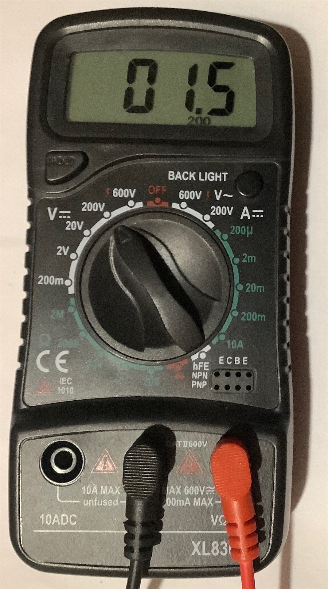
This is the setting on the multimeter I used for the resistors, which setting should I have actually used? Really sorry for my ignorance on this...
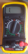
The meter didn't make any kind of bleeping noise when I was taking the measurements.
dhr
EDIT: I'm reading the manual for my multimeter now... I'll try re-taking the readings in a moment once I've worked out what I might have done wrong.
This is the setting on the multimeter I used for the resistors, which setting should I have actually used? Really sorry for my ignorance on this...
The meter didn't make any kind of bleeping noise when I was taking the measurements.
dhr
EDIT: I'm reading the manual for my multimeter now... I'll try re-taking the readings in a moment once I've worked out what I might have done wrong.
-
1024MAK
- Bugaboo
- Posts: 3136
- Joined: Wed Nov 15, 2017 2:52 pm
- Location: Sunny Somerset in the U.K. in Europe
Re: Speccy 48k issue 3b: Red and black screen
No need to worry, I just wanted to check. You don't have to do them again.
Mark
Mark
“There are four lights!”
Step up to red alert. Sir, are you absolutely sure? It does mean changing the bulb
Looking forward to summer later in the year.
-
dust hill resident
- Dizzy
- Posts: 52
- Joined: Sat Sep 23, 2023 6:05 pm
- Location: London
- Contact:
Re: Speccy 48k issue 3b: Red and black screen
Oh! I was worried the info I posted was wrong/irrelevant, I'm glad if it's okay after all.
I wonder, what should we do from here? Are there any other things to check or measure, or is it time to consider replacing IC3 and/or IC4?
dhr
I wonder, what should we do from here? Are there any other things to check or measure, or is it time to consider replacing IC3 and/or IC4?
dhr
Re: Speccy 48k issue 3b: Red and black screen
It looks like continuity beeper on your meter is 2 notches anticlockwise from the setting on the image you posted. The icon looks like a wifi signal, but might be a speaker? You should try it, a beep on continuity is a very useful feature. My old-but-good meter doesn't have it and I miss it when using that one.dust hill resident wrote: ↑Thu Oct 26, 2023 5:33 pm Oh! I was worried the info I posted was wrong/irrelevant, I'm glad if it's okay after all.
I wonder, what should we do from here? Are there any other things to check or measure, or is it time to consider replacing IC3 and/or IC4?
I think you still need to check the resistance across each of those resistors, as per Mark's post yesterday:
"Switch your multimeter to the resistance (range 2kΩ 2000Ω or equivalent) and test the resistance of the following resistors (test between the two leads of each resistor): R17, R18, R19, R20, R21, R22, R23 and R32. All should be around 330Ω apart from R32 which should be 100Ω"
I don't know how to interpret the results of a diagnostic ROM which is reporting IC3/4 failures. I'm hoping someone's going to explain it. Then again, if replacing those is the next step, since Retroleum have them at 99p each it might just be easier to replace them both. But wait for Mark to guide you. I'm interested to know what's next in the process as well.
Derek Fountain, author of the ZX Spectrum C Programmer's Getting Started Guide and various open source games, hardware and other projects, including an IF1 and ZX Microdrive emulator.
-
dust hill resident
- Dizzy
- Posts: 52
- Joined: Sat Sep 23, 2023 6:05 pm
- Location: London
- Contact:
Re: Speccy 48k issue 3b: Red and black screen
Ohh, I know about the continuity option, that's about the only feature on the multimeter that I feel confident that I know how to use at all, heheh. When I use that it does beep when I press the probes against a wire or piece of metal (or touch the probes directly together).dfzx wrote: ↑Thu Oct 26, 2023 8:02 pm It looks like continuity beeper on your meter is 2 notches anticlockwise from the setting on the image you posted. The icon looks like a wifi signal, but might be a speaker? You should try it, a beep on continuity is a very useful feature. My old-but-good meter doesn't have it and I miss it when using that one.
I used that option the other day when I was testing the traces on the board, but I wasn't using it last night when I took the (incorrect?) readings I posted - for that, I was using the option/rotary switch setting that's shown in the photo.
I think I'm confused about the instructions, because I thought I was doing what Mark said to do. I switched the multimeter rotary switch to the option that says something that looks like "2kΩ" and then I put the probes on the resistor legs and chip legs as directed, and then read off what was on the multimeter LCD screen.dfzx wrote: ↑Thu Oct 26, 2023 8:02 pm
I think you still need to check the resistance across each of those resistors, as per Mark's post yesterday:
"Switch your multimeter to the resistance (range 2kΩ 2000Ω or equivalent) and test the resistance of the following resistors (test between the two leads of each resistor): R17, R18, R19, R20, R21, R22, R23 and R32. All should be around 330Ω apart from R32 which should be 100Ω"
In order to check the resistance as directed, which option on the multimeter rotary switch should I select? And how will I be able to tell when I have it set correctly in order to get the proper readings that we need?
dhr
-
1024MAK
- Bugaboo
- Posts: 3136
- Joined: Wed Nov 15, 2017 2:52 pm
- Location: Sunny Somerset in the U.K. in Europe
Re: Speccy 48k issue 3b: Red and black screen
Give me a little time and I’ll post a photo…
“There are four lights!”
Step up to red alert. Sir, are you absolutely sure? It does mean changing the bulb
Looking forward to summer later in the year.
-
1024MAK
- Bugaboo
- Posts: 3136
- Joined: Wed Nov 15, 2017 2:52 pm
- Location: Sunny Somerset in the U.K. in Europe
Re: Speccy 48k issue 3b: Red and black screen
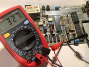
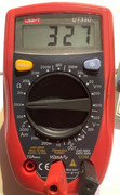

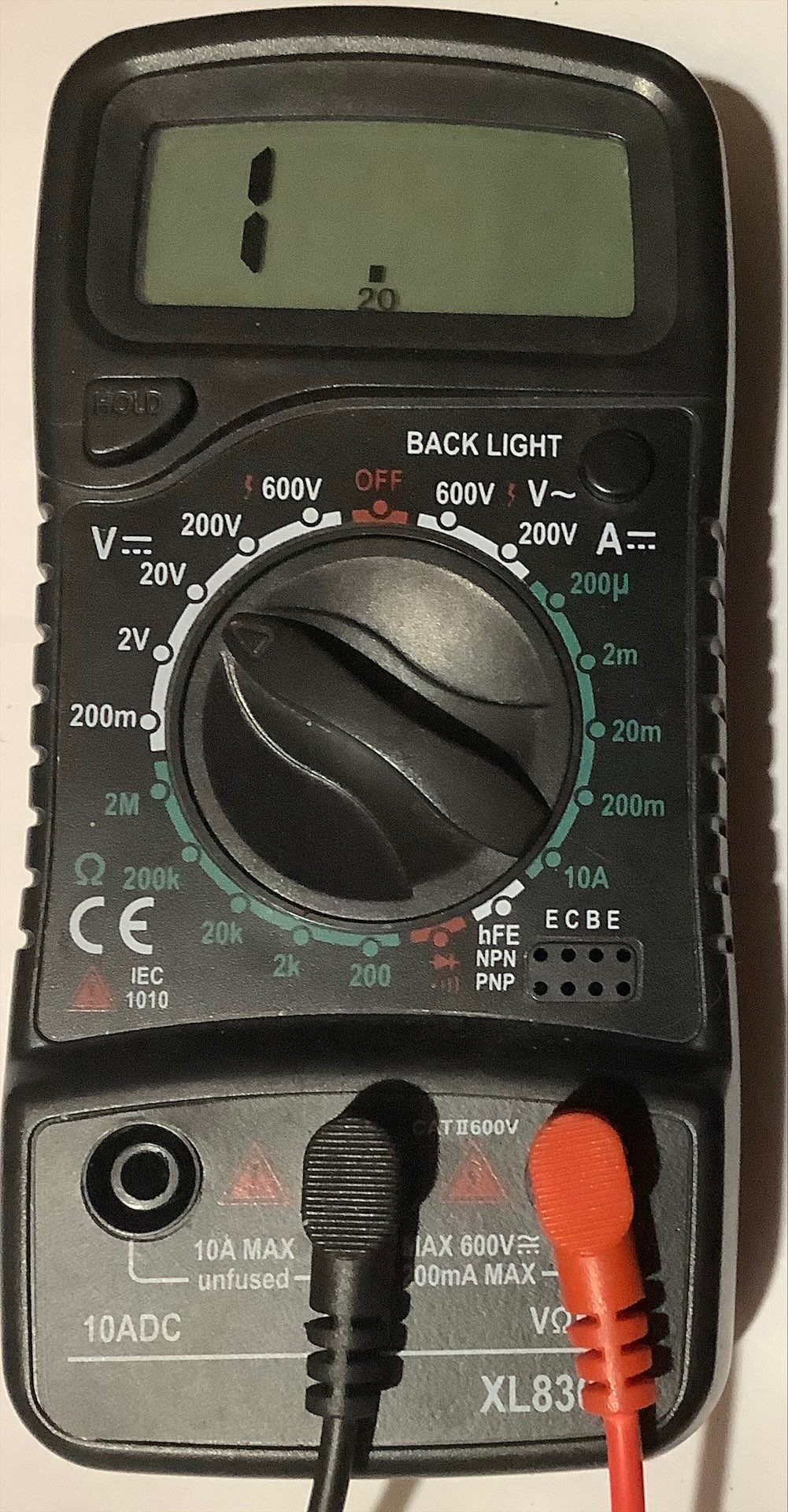
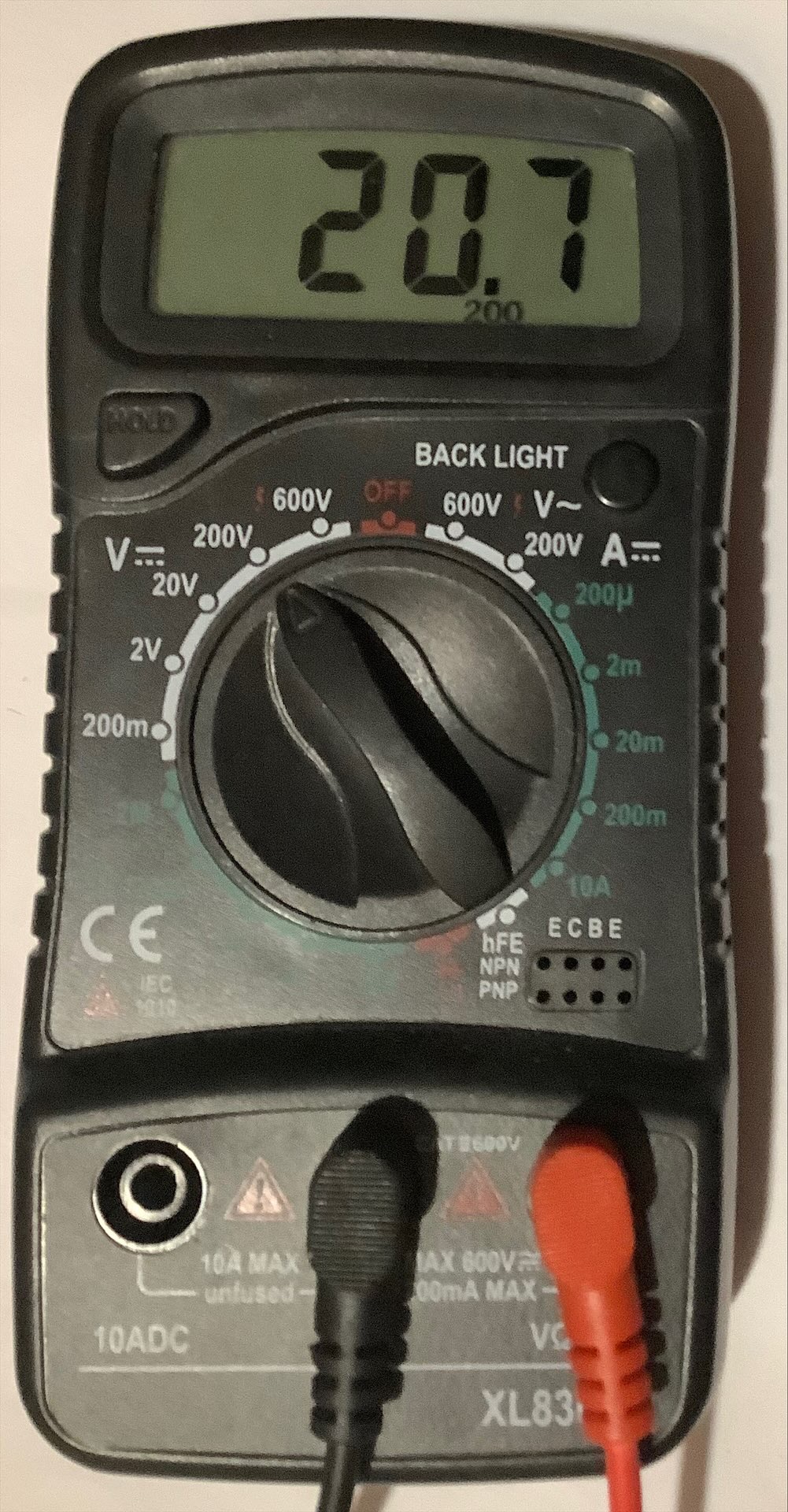
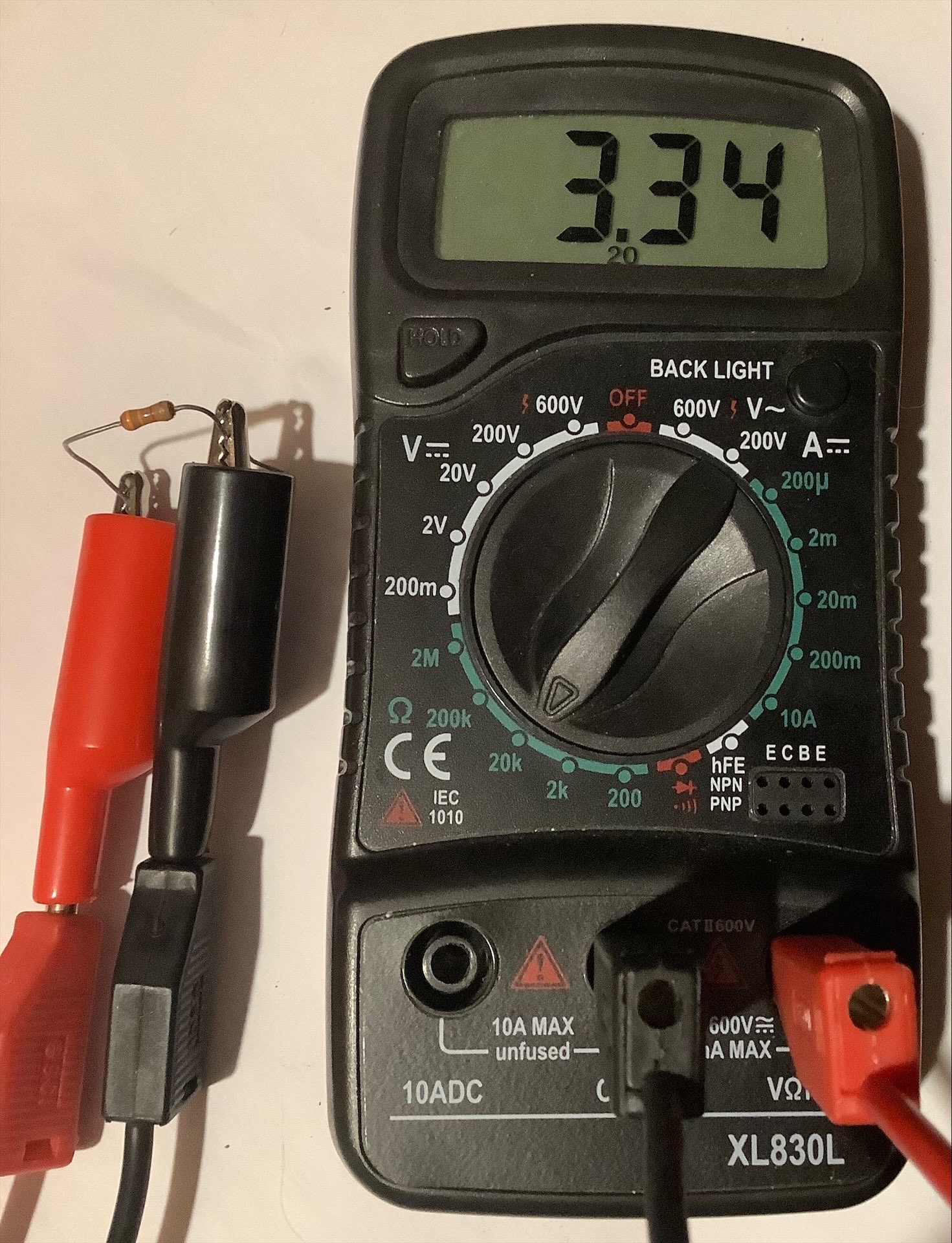
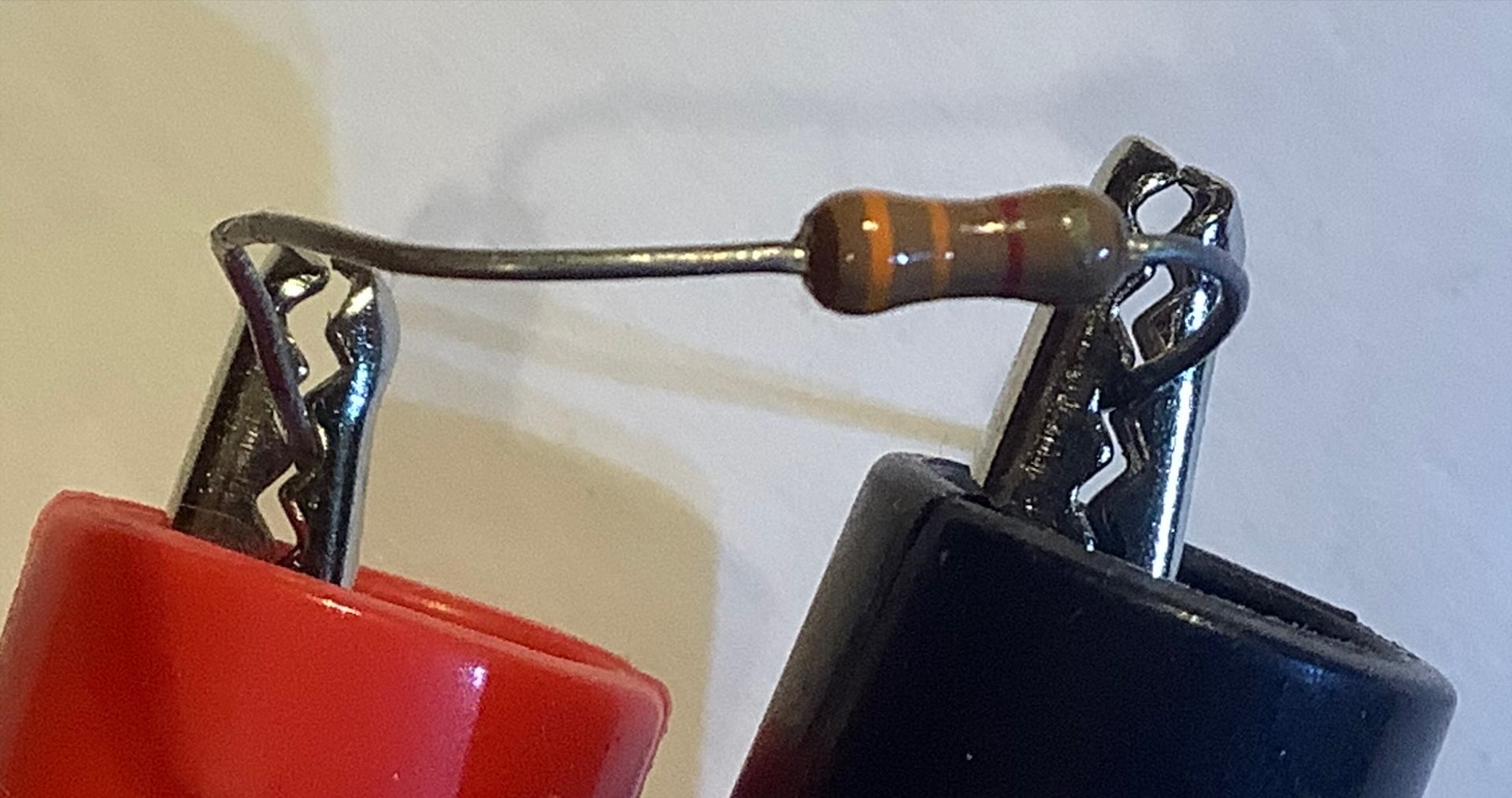
Photos show me measuring a 330Ω resistor using the 2000Ω range on an inexpensive multimeter. This is on an issue one board, I picked the easiest 330Ω resistor as an example, it’s not supposed to represent where the resistors are on other issue boards.
Mark
“There are four lights!”
Step up to red alert. Sir, are you absolutely sure? It does mean changing the bulb
Looking forward to summer later in the year.
-
1024MAK
- Bugaboo
- Posts: 3136
- Joined: Wed Nov 15, 2017 2:52 pm
- Location: Sunny Somerset in the U.K. in Europe
Re: Speccy 48k issue 3b: Red and black screen
While we are here, the colour bands give the value of the resistor. Typically, I’ve picked one where it’s the opposite way round to the way you read it!

So with this type, it’s best to look for the tolerance band, in this case, gold for 5% tolerance. Now read the value from the other direction…
Hence we have Orange (meaning 3)
Another Orange (also meaning 3)
And then Brown (here, a multiplier meaning times 10)
So the value is 33 X 10 = 330 in ohms.
Here’s one of about a zillion of resistor colour code charts/guides/tutorials available on the tinterweb https://www.electronicsforu.com/electro ... olour-code
Mark
“There are four lights!”
Step up to red alert. Sir, are you absolutely sure? It does mean changing the bulb
Looking forward to summer later in the year.
-
dust hill resident
- Dizzy
- Posts: 52
- Joined: Sat Sep 23, 2023 6:05 pm
- Location: London
- Contact:
Re: Speccy 48k issue 3b: Red and black screen
Ah! Thank you a lot Mark, I feel like I'm starting to understand. I was able to set my meter to that setting and measure the values of the resistors:
dhr
Code: Select all
r20 		325
r17 		323
r21 		325
r23 		327
r19 		326
r22 		324
r18 		324

r32 		104
-
dust hill resident
- Dizzy
- Posts: 52
- Joined: Sat Sep 23, 2023 6:05 pm
- Location: London
- Contact:
Re: Speccy 48k issue 3b: Red and black screen
I also had a thought that I've been wondering about. I've heard that in some cases, you can tell when a specific IC is bad because it gets abnormally hot.
So tonight I left the system switched on for a few minutes and then carefully tried touching the tops of IC3 and IC4 to sense how warm they get. They don't really get noticably warm at all.
But the ULA gets fairly warm quite quickly. It's not hot enough to burn my finger but it feels uncomfortably hot, like, you wouldn't want to leave your finger on it for long. It's definitely the warmest chip on the board by a fair bit.
Is this normal for the ULA?
dhr
Re: Speccy 48k issue 3b: Red and black screen
Yes, the ULA becomes hot by design. No need to be worry.
-
1024MAK
- Bugaboo
- Posts: 3136
- Joined: Wed Nov 15, 2017 2:52 pm
- Location: Sunny Somerset in the U.K. in Europe
Re: Speccy 48k issue 3b: Red and black screen
Yes, but, it’s when a chip runs hotter than normal, so you need to know if a chip normally runs cold, warm or hot!dust hill resident wrote: ↑Fri Oct 27, 2023 12:22 am I've heard that in some cases, you can tell when a specific IC is bad because it gets abnormally hot.
Mainly, it’s DRAM that fails in such a way that they run significantly hotter.
The ULA always runs warm/hot due to its design (there are various technologies used). Indeed, the manufacturer states that its internal temperature can be up to 125°C.
Those resistance readings are all okay.
I’ll post the next steps later.
Mark
“There are four lights!”
Step up to red alert. Sir, are you absolutely sure? It does mean changing the bulb
Looking forward to summer later in the year.
-
dust hill resident
- Dizzy
- Posts: 52
- Joined: Sat Sep 23, 2023 6:05 pm
- Location: London
- Contact:
Re: Speccy 48k issue 3b: Red and black screen
Thank you Mad Fritz and Mark, that's reassuring to know. It's pretty surprising how hot it gets!
dhr
Thank you a lot, I'm looking forward to investigating further.I’ll post the next steps later.
dhr
-
1024MAK
- Bugaboo
- Posts: 3136
- Joined: Wed Nov 15, 2017 2:52 pm
- Location: Sunny Somerset in the U.K. in Europe
Re: Speccy 48k issue 3b: Red and black screen
Well, keeping in mind that the internal logic of the ULA actually runs at a little under 1V. And this logic is based on bipolar transistor technology. The ULA actually has two supply inputs. One feeds the internal interface circuitry that communicates with the outside world. The other feeds a bunch of internal series type voltage regulators.
In comparison, most modern chips use low power CMOS technology, so unless they are running at a very high speed, they typically run “cold”.
Before we get to the next step, a little bit of instruction on using a manual range multimeter.
Lets do voltage testing first. The objective is to select the best range to give the most accurate reading within the limitations of the multimeter, but without damaging it or injuring yourself.
Before using a multimeter, it’s good practice to at least test the test leads. Use the 200Ω resistance range to check that the resistance of the leads is low (under 2Ω).
When testing a DC voltage, you can also test a known voltage, for example, the voltage of a battery or cell.
When testing where the voltage is unknown, always start at the highest voltage range. Then work your way down to the most suitable range.
Multimeters don’t work on magic. They need a little bit of power from the circuit under test. And the circuitry they use is not perfect, hence although the basic accuracy is good, they can, and do give inconsistent results at times. Especially if the user doesn’t use best practice when using them.
So, the most suitable range, what does that mean?
Your multimeter and hundreds of others, use a 3½ digit display. This means that the left hand digit can only show a blank (or a zero) or a 1. The remaining digits can show any number. Hence the maximum number that the display can show is 1999.
Add in the use of the decimal point and you get 1.999, 19.99 and 199.9.
Now look at the available voltage ranges on your meter (I’m leaving out the 600V range, I’ll explain later): 200mV, 2V, 20V, 200V.
Now, we need to talk about resolution. If you test a 1.5V cell (battery) on the 2V range, if the actual voltage is 1.455V, if you meter is perfectly accurate, on this range it should show 1.455V. Great, every one is happy! Back in the real world, the least significant digit may show something else.
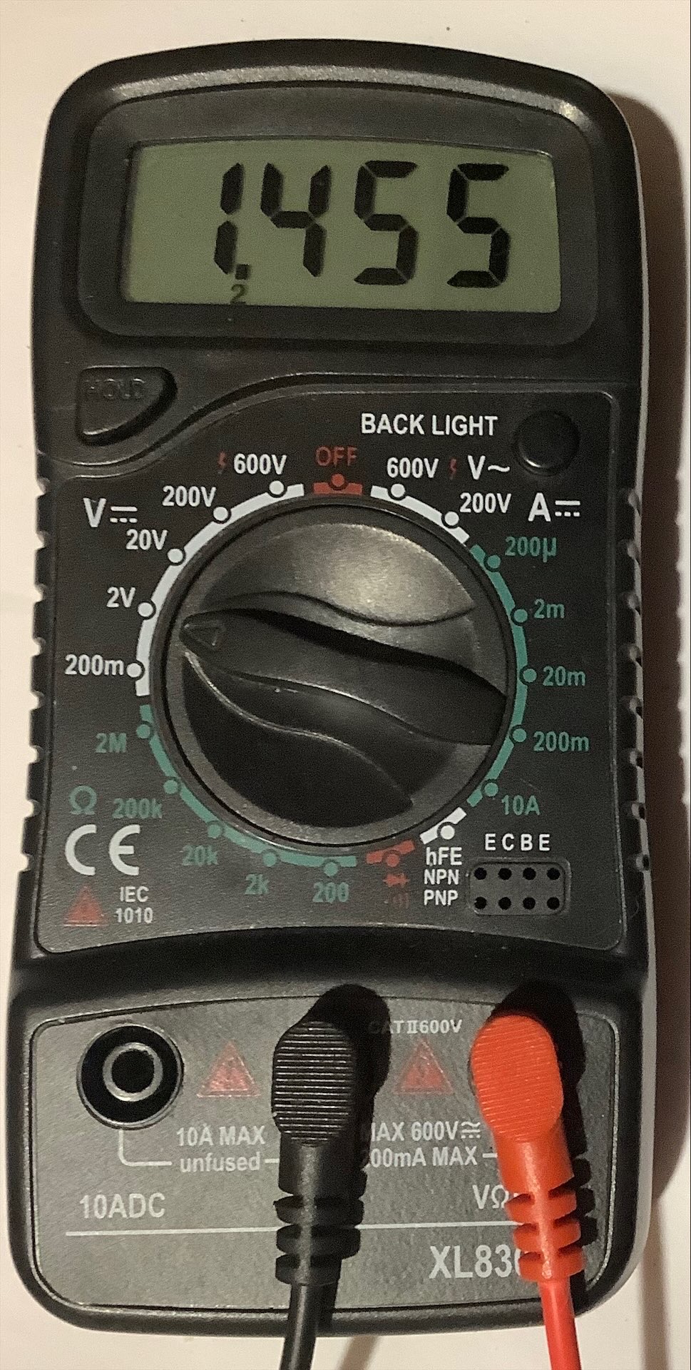
Now look at what happens if you use the 200V range. The meter will likely show 1.5V, it may show 1.4V or flick between these two values. Or it may show something different depending on how accurate it is. You see, the least significant digit will not always show the result you expect. This is due to it being affected by the actual accuracy the meter can manage and being subject to rounding. On this range you are also wasting the other digits.
Hence, the most suitable range, is the range where the most digits are being used. But without going down to a range which is too low for the actual voltage.
So for example, if the voltage is 20.62V, the 20V range is no good, the meter instead will either just show “1” in the left hand digit, it may flash this digit or on more expensive meters, it may display OL.
So the most suitable range is the 200V range. The meter hopefully will show 20.6V, but may show 20.7V as it only has three digits that can be used for this voltage.
Okay, why did I exclude the 600V range? Because, this figure is (apparently) based on the maximum safe voltage that the meter can test. Not on the maximum value that the display can show. However, a lot of inexpensive multimeters do not comply with UK recommended electrical standards in their construction. So I don’t recommend using them on mains voltages or anything higher.
The resistance range is similar, but, there is no problem with any danger or damage from getting the “wrong” range.
However, there is a difference. Any resistance above the value that can be shown on the meter using the current range is treated as infinitely. The meter shows this “1” in the left hand digit, it may flash this digit or on more expensive meters, it may display OL.
Otherwise, the principle of using the most suitable range applies as before.
Because there is no problem with any danger or damage from getting the “wrong” range, if you don’t know the resistance, you can start in the middle range. So with your meter, that’s the 20kΩ range.
Now is a good time to point out that the displayed value is only part of the result. You have to include the range in combination with the decimal point. If you have a 3.3kΩ resistor, the meter will (assuming it’s perfectly accurate) show 3.30 on its display. But the resistor is not 3.3Ω. Instead when you combine the two, the meter is really saying that the resistor is 3.3kΩ.
Anyway, back to testing… So test on the 20kΩ range, if you get the over-range/infinitely display, move up to the next range. If digits are being wasted, move down a range, then repeat if needed.
I mention this, because for the next test you may need to know this information.
But before moving on, we need to talk about how the meter tests resistance. This is relevant, because we, or rather you will be testing circuits that contain semiconductor junctions integrated circuits (ICs or chips…).
Lets start with testing a simple resistor that is not connected to any circuit. The modern multimeter puts out a low test current on its positive (red) terminal. The current flows through the resistor back to the negative (black) terminal. The meter can now measure the voltage between its terminals.
With a meter similar to yours (meter #1), on the 20kΩ range, with a 3.3k resistor, I measure the voltage across the resistor while being tested on resistance as 65mV using a second meter (meter #2). The test current from meter #1 as measured on meter #2 was 19.4uA. If you do the mathematics, you can see how this works, it’s alright, I’ll spare you for now!
With no resistance connected, the open circuit test voltage is 274mV. On the 200kΩ and 2MΩ ranges, the open circuit test voltage is similar.
However, on the 200Ω and 2kΩ ranges, the test voltage (on my model of multimeter) is around 2.86V.
Why am I going into all these technical details? No, it’s not to blow your mind, honest.
It’s because semiconductor junctions start to turn on at around 0.5V or greater. This is why on some of these meters, you will have a diode symbol on the 2kΩ range, because you can also use it to test diodes. It will also light some LEDs (such as red ones).
So please keep this in mind, don’t use the 200Ω and 2kΩ ranges if it’s likely that a semiconductor junction may turn on, as you then get misleading results. Unless of course you actually want the junction to turn on… But then the value shown is not a true resistance value.
Okay, now breathe…
Back soon…
Mark
PS, yes, that went on a bit longer than I first intended, so sorry if it’s a bit long…
“There are four lights!”
Step up to red alert. Sir, are you absolutely sure? It does mean changing the bulb
Looking forward to summer later in the year.
Re: Speccy 48k issue 3b: Red and black screen
It looks like it's doing the lower ram test and it fails. So some lower ram chips failing probably. I mean, couldn't they just have died when changing the capacitors?
Re: Speccy 48k issue 3b: Red and black screen
@1024MAK
Apart from the fact that that all your posts are showing your deep technological knowledge:
Your patience espeacilly with newbies is just admireable.
I am glad to have you here in this forum, just in case...
Many Thanks
Apart from the fact that that all your posts are showing your deep technological knowledge:
Your patience espeacilly with newbies is just admireable.
I am glad to have you here in this forum, just in case...
Many Thanks
-
dust hill resident
- Dizzy
- Posts: 52
- Joined: Sat Sep 23, 2023 6:05 pm
- Location: London
- Contact:
Re: Speccy 48k issue 3b: Red and black screen
Agreed 100%, thank you so much Mark for the info, I appreciate it so much and I've been reading what you wrote and thinking about it. I even took out an LED from my box of random bits and tried the 2kΩ setting on my multimeter with it, and just like you said, it made it light up! Really cool!
No need to be sorry at all, rather, I'm really grateful for the thought you're putting in in explaining things. I want to learn and understand, I've long wanted to get into electronics but it's always been tricky for me to get started.PS, yes, that went on a bit longer than I first intended, so sorry if it’s a bit long…
From my intuition, I'm starting to feel like the RAM itself might not be the problem because none of the ram chips get hot, and the behaviour of my system doesn't match the descriptions of common RAM failure patterns described on this page: https://spectrumforeveryone.com/feature ... nja-style/
The strange mirroring/repeating of text lines when running DiagROM makes me wonder too, is it possible for failed RAM chips to produce that kind of effect?
I'm cautious to draw any conclusions at all though except that the lower RAM is a suspect. I'm eager to continue investigating and hopefully narrowing things down.
dhr
-
1024MAK
- Bugaboo
- Posts: 3136
- Joined: Wed Nov 15, 2017 2:52 pm
- Location: Sunny Somerset in the U.K. in Europe
Re: Speccy 48k issue 3b: Red and black screen
So, to the next steps.
With the power disconnected, and with your multimeter set to the 2MΩ resistance range, put your black (negative) probe on any convenient 0V/GND connection (e.g. IC3 or IC4 pin 8) and leave it there.
Then using your red (positive) probe, test each of these pins in turn:
IC3 pin 4, 7, 9 and 12
IC4 pin 4, 7, 9 and 12
Please list your results.
Now put your red (positive) probe on any convenient +5V connection (e.g. IC3 or IC4 pin 16) and leave it there.
Using your black (negative) probe , test each of these pins in turn:
IC3 pin 4, 7, 9 and 12
IC4 pin 4, 7, 9 and 12
Please list your results.
Mark
“There are four lights!”
Step up to red alert. Sir, are you absolutely sure? It does mean changing the bulb
Looking forward to summer later in the year.
-
dust hill resident
- Dizzy
- Posts: 52
- Joined: Sat Sep 23, 2023 6:05 pm
- Location: London
- Contact:
Re: Speccy 48k issue 3b: Red and black screen
Here are the results:1024MAK wrote: ↑Sun Oct 29, 2023 5:49 pm With the power disconnected, and with your multimeter set to the 2MΩ resistance range, put your black (negative) probe on any convenient 0V/GND connection (e.g. IC3 or IC4 pin 8) and leave it there.
Then using your red (positive) probe, test each of these pins in turn:
IC3 pin 4, 7, 9 and 12
IC4 pin 4, 7, 9 and 12
Please list your results.
IC3
Pin4 .000
Pin7 .820
Pin9 .816
Pin12 .813
IC4
Pin4 .817
Pin7 .810
Pin9 .842
Pin12 .808
Here are the results:
IC3
Pin4 .001
Pin7 .619
Pin9 .623
Pin12 .610
IC4
Pin4 .613
Pin7 .628
Pin9 .633
Pin12 .614
I'm noticing the reading from pin 4 on IC3 is very different from all the others. To be sure, I checked this pin multiple times. The readings were the same each time. I wonder what's happening here.
dhr
Re: Speccy 48k issue 3b: Red and black screen
Doesn't that imply that the output pin 4 of IC3 is shorted to both GND and +5V at the same time?dust hill resident wrote: ↑Sun Oct 29, 2023 7:59 pm Here are the results:
IC3
Pin4 .000
Here are the results:
IC3
Pin4 .001
I wonder what's happening here.
I can imagine that an IC might fail internally such that a pin shorts to GND or VCC, but ... both together?
Derek Fountain, author of the ZX Spectrum C Programmer's Getting Started Guide and various open source games, hardware and other projects, including an IF1 and ZX Microdrive emulator.
-
dust hill resident
- Dizzy
- Posts: 52
- Joined: Sat Sep 23, 2023 6:05 pm
- Location: London
- Contact:
Re: Speccy 48k issue 3b: Red and black screen
Ohh hmm... could this mean I was doing something wrong? Like, touching the wrong pin or something else? I'll try re-doing this measurement later tonight...
-
1024MAK
- Bugaboo
- Posts: 3136
- Joined: Wed Nov 15, 2017 2:52 pm
- Location: Sunny Somerset in the U.K. in Europe
Re: Speccy 48k issue 3b: Red and black screen

You are testing the output pins.
Also, switch down to the 20kΩ range if the reading on the 2MΩ range is low.
Mark
“There are four lights!”
Step up to red alert. Sir, are you absolutely sure? It does mean changing the bulb
Looking forward to summer later in the year.
Re: Speccy 48k issue 3b: Red and black screen
No, no, I wasn't suggesting you hadn't done the test properly.dust hill resident wrote: ↑Sun Oct 29, 2023 9:05 pm Ohh hmm... could this mean I was doing something wrong? Like, touching the wrong pin or something else? I'll try re-doing this measurement later tonight...
I'm following along, trying to learn and understand the process Mark is taking you through. This test appears to be checking whether the outputs of the multiplexers have somehow been permanently shorted to either GND or +5V. Your results suggest both for one output pin! I can see that might happen if the internals of the device have melted into a blob, but it also seems to imply that there's now a direct connection between +5V and GND inside the chip which would cause a very high current draw.
My post was kind of wondering aloud whether that sort of failure can happen and what the result might be if it did...
Derek Fountain, author of the ZX Spectrum C Programmer's Getting Started Guide and various open source games, hardware and other projects, including an IF1 and ZX Microdrive emulator.