Speccy 48k issue 3b: Red and black screen

For experts to discuss very technical stuff and newbies to ask why the Spectrum they bought off ebay doesn't work.
User avatar
dust hill resident
Dizzy
Posts: 52
Joined: Sat Sep 23, 2023 6:05 pm
Location: London
Contact:

Speccy 48k issue 3b: Red and black screen

Post by dust hill resident »

Hi all,

I got a Spectrum 48k off of ebay recently, and thought I'd re-cap as a safety precaution and also because the video display was noisy.
It was otherwise in working condition.

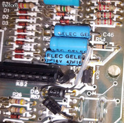
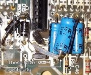
I very carefully replaced all of the capacitors using the kit sold by retroleum (so the replacement capacitors themselves are guaranteed to be good quality)
and I tested that the system still worked after each couple of capacitors I fitted.
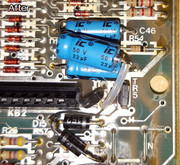
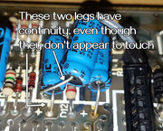
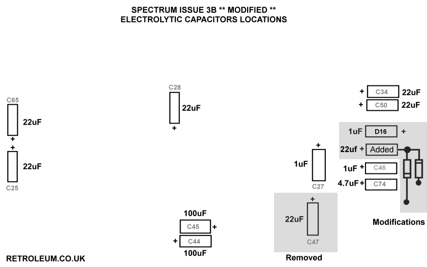
It was all working fine until the very last three capacitors were fitted, which were C46, C47, and the 'added' capacitor (see here http://blog.retroleum.co.uk/wp-content/ ... layout.png )
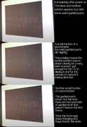
and that's when the red and black screen started.

So far all the research I've done suggests that this is a lower memory failure of some sort. Following the suggestions here ( viewtopic.php?t=1216 )
I used my multimeter to try to check the voltages. I'm not very confident with this stuff but I looked up the data sheet online for the RAM chips and looked up the specified voltage values, and poked the black probe to ground and the red probe to pins on the chips and sure enough, I got readings of values that looked like the ones on the data sheet, pretty much around 12, 5, -5. (let me know if you're interested in the precise values and I'll post them) so maybe the power side of things is working properly.

I wonder, what should I try next?
Image

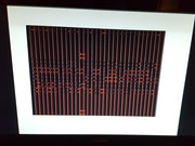
I'll post a video in a minute so you can see exactly what it looks like before it reaches this screen, things move a little bit and maybe that's important diagnostic information.

Thank you all a lot,
dhr
User avatar
dust hill resident
Dizzy
Posts: 52
Joined: Sat Sep 23, 2023 6:05 pm
Location: London
Contact:

Re: Speccy 48k issue 3b: Red and black screen

Post by dust hill resident »

Here's a video of the spectrum being powered on:


I power it on and off a few times so you can see how the screen changes a little bit before it settles.

Edit:
Here's a photo of the board in its current state, in case it helps:
Image
User avatar
1024MAK
Bugaboo
Posts: 3130
Joined: Wed Nov 15, 2017 2:52 pm
Location: Sunny Somerset in the U.K. in Europe

Re: Speccy 48k issue 3b: Red and black screen

Post by 1024MAK »

Yes, please provide the exact voltages of the +5V, -5V and +12V supplies. And please confirm if you are testing on the pins of IC13 (the left most 4116 or equivalent DRAM chip). The -5V voltage and polarity is important.

Also the (nominal) +9V voltage (test on the DC input socket or on the replacement for the 7805 voltage regulator, left hand leg, the centre pin is the 0V/ground/common).

Have you fitted the 'added' capacitor exactly as per the original capacitor? And neither leg is touching any nearby components?

Can you read and follow schematic diagrams?

Mark
:!: Standby alert :!:
“There are four lights!”
Step up to red alert. Sir, are you absolutely sure? It does mean changing the bulb :dance
Looking forward to summer later in the year.
User avatar
dust hill resident
Dizzy
Posts: 52
Joined: Sat Sep 23, 2023 6:05 pm
Location: London
Contact:

Re: Speccy 48k issue 3b: Red and black screen

Post by dust hill resident »

Hi Mark,

I just tested it again and took all the readings. I'm not sure if I measured the voltage from the replacement for the 7805... I put the black probe on ground and the red probe on either the right and left leg of the regulator to get the readings, is that right? I notice I got +12.09 and +5.00 for that, and not 9... perhaps a problem?

I tested ic13 like you said, but also to be sure I tested all the other memory chips to the right too, they all gave precisely the same reading.

Code: Select all

ic13 (and all of the other 4116 chips too)
 vbb (top left)
  -5.13
 vdd (bottom left)
  +12.09
 vcc (bottom right)
  +5.00
 
voltage regulator
 left leg (towards the loudspeaker)
  +11.57
 right leg (away from the loudspeaker)
  +5.01
About the capacitors,
Have you fitted the 'added' capacitor exactly as per the original capacitor? And neither leg is touching any nearby components?
I took great care to re-fit the new capacitors in precisely the same way the old ones were fitted, triple and quadruple checking everything every step of the way, especially in that area. I was a little nervous about that area because of how cramped it is, and because it seems a little different from the other parts of the board - if I understand right, isn't it a later modification that was done by the manufacturers to improve reliability of the power circuit? that'd be consistent with how it looks visually, it feels a bit "hacky" maybe.

So I took photos before I did anything and cross referenced the photos while I worked. Here's the area before:
Image
And after:
Image
It's very tight there... But visually inspecting the area closely (hard to show in photos), it looks like the legs aren't touching each other.
And looking underneath on the other side of the board, I don't think I see any blobs of solder bridging anything... (I'll post a photo of the underside in a min)

However, testing with the multimeter, I notice that these two legs have continuity - is that a problem? Or are they connected deliberately by traces in the board as part of the intended design?
Image

Something I was nervous about when fitting the 'added' capacitor was whether or not it would make the connection with the other bits it's supposed to be connected with via that thin black wire (that was there originally) which connects to the spot where the negative leg of that capacitor connects to the board. But my multimeter buzzes when testing for continuity between the negative leg of the added capacitor and the junction the black wire connects to, so perhaps that's all good and correct?
Image

Let me know if you need any more info! Thank you a lot for helping.
Can you read and follow schematic diagrams?
I can't, but I'm prepared to learn and would like to learn how.

Thank you,
dhr
User avatar
dust hill resident
Dizzy
Posts: 52
Joined: Sat Sep 23, 2023 6:05 pm
Location: London
Contact:

Re: Speccy 48k issue 3b: Red and black screen

Post by dust hill resident »

Here's the underside of the board:
Image
User avatar
1024MAK
Bugaboo
Posts: 3130
Joined: Wed Nov 15, 2017 2:52 pm
Location: Sunny Somerset in the U.K. in Europe

Re: Speccy 48k issue 3b: Red and black screen

Post by 1024MAK »

dust hill resident wrote: Sat Oct 21, 2023 12:43 pm I just tested it again and took all the readings. I'm not sure if I measured the voltage from the replacement for the 7805... I put the black probe on ground and the red probe on either the right and left leg of the regulator to get the readings, is that right? I notice I got +12.09 and +5.00 for that, and not 9... perhaps a problem?
Yes, that’s why I said “the (nominal) +9V voltage”. The Sinclair UK1400 / EU1400 (or equivalent) power supply units (PSU) are unregulated types. The output voltage depends on how much current they are supplying. The output voltage is only approximately 9V at the full load current. Otherwise the output voltage will be higher, typically between 10.5V and 12.5V approximately. The output voltage is also dependent on the actual mains voltage.

Anyway, all the supply voltages are okay.

I’ll read on and reply about the rest of your post later.

Mark
:!: Standby alert :!:
“There are four lights!”
Step up to red alert. Sir, are you absolutely sure? It does mean changing the bulb :dance
Looking forward to summer later in the year.
User avatar
1024MAK
Bugaboo
Posts: 3130
Joined: Wed Nov 15, 2017 2:52 pm
Location: Sunny Somerset in the U.K. in Europe

Re: Speccy 48k issue 3b: Red and black screen

Post by 1024MAK »

dust hill resident wrote: Sat Oct 21, 2023 12:43 pm About the capacitors,

I took great care to re-fit the new capacitors in precisely the same way the old ones were fitted, triple and quadruple checking everything every step of the way, especially in that area.
Excellent 👍 
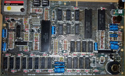
And you took photos before starting work 👍😁
dust hill resident wrote: Sat Oct 21, 2023 12:43 pm I was a little nervous about that area because of how cramped it is, and because it seems a little different from the other parts of the board - if I understand right, isn't it a later modification that was done by the manufacturers to improve reliability of the power circuit? that'd be consistent with how it looks visually, it feels a bit "hacky" maybe.
Actually, this part of the circuitry (the DC/DC converter) had many changes over the various issue boards and in between different issue boards…
The modification was either performed at the factory, or by service engineers either when the computer was repaired, serviced or returned for any other reason. It looks a bit hacky because they added additional components and changed some of the existing components for different ones. Some modifications look worse than others.
dust hill resident wrote: Sat Oct 21, 2023 12:43 pm However, testing with the multimeter, I notice that these two legs have continuity - is that a problem? Or are they connected deliberately by traces in the board as part of the intended design?
Yes, the positive leads of these two capacitors (C46 and the extra capacitor, also known, depending on board version as C78 or C80) are connected via the PCB tracks. So you will get continuity.
dust hill resident wrote: Sat Oct 21, 2023 12:43 pm Something I was nervous about when fitting the 'added' capacitor was whether or not it would make the connection with the other bits it's supposed to be connected with via that thin black wire (that was there originally) which connects to the spot where the negative leg of that capacitor connects to the board. But my multimeter buzzes when testing for continuity between the negative leg of the added capacitor and the junction the black wire connects to, so perhaps that's all good and correct?
That’s correct and okay.

Okay, now that we have established that the on board power supply circuitry is okay (which are like the foundations of electronic systems), we now need to work out what else is working or not working.

The start of this video shows the affect on the ZX Spectrum screen at power up if it’s working correctly. Keep in mind this is an emulator, so won’t show the random coloured squares that you may see momentarily immediately after power on.


Run it at 0.25 speed to see the sequence more clearly.

More later…

Mark
:!: Standby alert :!:
“There are four lights!”
Step up to red alert. Sir, are you absolutely sure? It does mean changing the bulb :dance
Looking forward to summer later in the year.
User avatar
dust hill resident
Dizzy
Posts: 52
Joined: Sat Sep 23, 2023 6:05 pm
Location: London
Contact:

Re: Speccy 48k issue 3b: Red and black screen

Post by dust hill resident »

That's a really good thought about the display at bootup on a normal working spectrum, I've been looking into that more. I used FUSE emulator to record this video clip of the 48k spectrum bootup at 10% speed to see what it does more clearly:


This page also has a really nice step by step description of what it does at boot: https://spectrumforeveryone.com/feature ... nja-style/

I've been looking at and reading up about this, while thinking about it and comparing with what my speccy is doing when I power it on, and making some observations:
Image

So far, it seems like my speccy is:
* Executing the first part of ROM (ROM and CPU might be okay)
* Entering the memory test and going wrong somewhere in there

dhr
User avatar
1024MAK
Bugaboo
Posts: 3130
Joined: Wed Nov 15, 2017 2:52 pm
Location: Sunny Somerset in the U.K. in Europe

Re: Speccy 48k issue 3b: Red and black screen

Post by 1024MAK »

So, my next question is, over the course of ten power up / power down, repeat.. cycles, does the border always end up white?

If yes, the Z80 is definitely executing the first bytes of the ROM.

If you don’t always get white, measure the voltage across capacitor C27 (1µF, between the Z80A/µPD780C-1 and the right hand keyboard connector). It should be at or nearly at +5V. If it is, briefly (between one and two seconds) short between the positive lead and the negative lead of capacitor C27. Don’t worry, this is perfectly safe, as long as you are connected to C27. This should reset the Z80 and in a working board, reset the computer to the copyright screen.

Mark
:!: Standby alert :!:
“There are four lights!”
Step up to red alert. Sir, are you absolutely sure? It does mean changing the bulb :dance
Looking forward to summer later in the year.
User avatar
dust hill resident
Dizzy
Posts: 52
Joined: Sat Sep 23, 2023 6:05 pm
Location: London
Contact:

Re: Speccy 48k issue 3b: Red and black screen

Post by dust hill resident »

So, my next question is, over the course of ten power up / power down, repeat.. cycles, does the border always end up white?
I just now tested it by powering on and off 10 times.
The border ends up white every single time, and not only that, but also the image that ends up on the screen is completely identical every time - precisely the exact same garbled black and red lines with precisely the same garbled stuff in the same place every time - it's perfectly consistent.
If you don’t always get white, measure the voltage across capacitor C27 (1µF, between the Z80A/µPD780C-1 and the right hand keyboard connector). It should be at or nearly at +5V. If it is, briefly (between one and two seconds) short between the positive lead and the negative lead of capacitor C27. Don’t worry, this is perfectly safe, as long as you are connected to C27. This should reset the Z80 and in a working board, reset the computer to the copyright screen.
Even though it's showing white border and an identical image on the screen every time, I feel this would be good to try still.
To make sure I understand you, when you say measure across C27 and the righthand keyboard connector - do you mean press the red lead or the black lead to the positive or negative leg of C27? Also, does it matter which pin from the keyboard connector I touch the other lead to? (sorry for my ignorance, I'm pretty new to electronics but really want to learn)

Image

dhr
User avatar
1024MAK
Bugaboo
Posts: 3130
Joined: Wed Nov 15, 2017 2:52 pm
Location: Sunny Somerset in the U.K. in Europe

Re: Speccy 48k issue 3b: Red and black screen

Post by 1024MAK »

dust hill resident wrote: Sat Oct 21, 2023 8:13 pm To make sure I understand you, when you say measure across C27 and the righthand keyboard connector - do you mean press the red lead or the black lead to the positive or negative leg of C27? Also, does it matter which pin from the keyboard connector I touch the other lead to? (sorry for my ignorance, I'm pretty new to electronics but really want to learn)
Meter red (positive) lead to capacitor C27 positive lead.
Meter black (negative) lead to capacitor C27 negative lead.
Measure the DC voltage.

I only mentioned the Z80A/µPD780C-1 and the right hand keyboard connector to ensure you knew which capacitor I was referring to.

Do not make any connection to the keyboard connector!

For the next step, use a wire to briefly short between capacitor C27 positive lead and negative lead. This capacitor is part of the processor reset circuit. If this capacitor is shorted out, you pull pin 26 of the processor to 0V/ground (a logic low). When the processor sees a logic low (or logic zero) on pin 26, it will perform an internal reset. The important point of this, is that it will start executing (machine code) instructions from memory location 0 (zero). In the ZX Spectrum, this memory location is in the ROM. This is the reset vector. Executing code here restarts BASIC.

Shorting C27 is safe because the feed from the +5V rail is via resistor R31. This resistor has a value of 220KΩ. This is a high value of resistance, and thus, it limits the current from the +5V rail. This is intentional. Because in normal operation, when the computer is powered up, the limited current through R31 means that it takes time for capacitor C27 to charge up. Hence the processor gets a ‘power up’ reset. This may be slow to the processor, but it’s still too quick for a human to see it on a multimeter (even if the multimeter was fast enough).

Also, in the ZX Spectrum+ models, which have a reset button (push switch), this is wired across capacitor C27.

Just to be clear, the ZX Spectrum uses a 8 bit microprocessor. The original design is by Zilog and is generally called a Z80. This is the generic name. This is made using NMOS technology. The first version (an actual Z80) was rated at 2.5MHz maximum clock speed. The next step up in the speed ratings is the Z80A. Although Zilog later renumbered their chips, but that’s a story for another day.

Because Zilog was originally a small company, they licensed other semiconductor manufacturers to also make Z80 microprocessors. Hence there were numerous manufacturers (sometimes called second sources).

However, the NEC company did not have a license. They were a bit naughty, and came up with their own design, that happens to be completely compatible with the Zilog Z80.

They used their own part numbering system. They called this processor µPD780C-1 and labelled the actual chips as D780C-1. The full part number (µPD780C-1) is used in the NEC documentation. A lot of NEC parts are not marked with the prefix “µP”.

Because it’s fully compatible, and was sold at competitive prices, Sinclair (and other computer manufacturers) used the µPD780C-1 as well as Zilog parts.

Mark
:!: Standby alert :!:
“There are four lights!”
Step up to red alert. Sir, are you absolutely sure? It does mean changing the bulb :dance
Looking forward to summer later in the year.
User avatar
dust hill resident
Dizzy
Posts: 52
Joined: Sat Sep 23, 2023 6:05 pm
Location: London
Contact:

Re: Speccy 48k issue 3b: Red and black screen

Post by dust hill resident »

1024MAK wrote: Sat Oct 21, 2023 9:38 pm Meter red (positive) lead to capacitor C27 positive lead.
Meter black (negative) lead to capacitor C27 negative lead.
Measure the DC voltage.

I only mentioned the Z80A/µPD780C-1 and the right hand keyboard connector to ensure you knew which capacitor I was referring to.

Do not make any connection to the keyboard connector!
Ahh I understand you now! Measuring the voltage across C27, my multimeter says +4.10 or +4.09. Is this maybe a bit low, or is it okay?

I carefully tested shorting the ends of C27 with a short piece of wire. Upon doing that, for a very brief instant I can see the screen redraw itself, similar to the observation I noted in my earlier post - it looks like the red lines are redrawn cleanly for a very brief moment, and then the garbled pattern appears again.

That's really interesting about the Z80 and the PD780C-1, I've known a little bit about the Z80 and that it's the CPU in the spectrum line of computers, but I didn't know which part on the spectrum board was the processor cos I didn't see anything marked "Z80". Now I know that the chip marked D780C -1 is the CPU!

That's really interesting as well about how C27 is responsible for resetting the processor at power on. I've often wondered how computers know how to start up from scratch after power on since I've been aware that, for example, memory is set to (essentially) random values at cold boot.

dhr
User avatar
1024MAK
Bugaboo
Posts: 3130
Joined: Wed Nov 15, 2017 2:52 pm
Location: Sunny Somerset in the U.K. in Europe

Re: Speccy 48k issue 3b: Red and black screen

Post by 1024MAK »

Okay, so we know for certain now, the processor is running the code from the ROM. Or at least some of it.

At this point it’s worth pointing out what we know and don’t know.

We know that these major chips are at least partially working, but don’t know yet if they are fully working:
Processor, ROM, ULA.

We also know that at least enough of the address, control and data busses are working so that the processor can read the first part of the code from ROM. But don’t know if all of the busses work fully.

We don’t know if enough to say anything about the RAM apart from its a suspect.

As recent work has taken place on the board, it’s worthwhile saying that now is a good time to carefully inspect both sides of the whole board using a good magnifying glass and a good light. You are looking for any solder splashes. Sometimes these can be as fine as a human hair. But also look for any cracks or breaks to the PCB copper tracks. Even if you have already checked, it’s still a good idea to check again. As it only takes a problem with one critical PCB track to cause the system to fail.

Mark
:!: Standby alert :!:
“There are four lights!”
Step up to red alert. Sir, are you absolutely sure? It does mean changing the bulb :dance
Looking forward to summer later in the year.
User avatar
dust hill resident
Dizzy
Posts: 52
Joined: Sat Sep 23, 2023 6:05 pm
Location: London
Contact:

Re: Speccy 48k issue 3b: Red and black screen

Post by dust hill resident »

1024MAK wrote: Sun Oct 22, 2023 5:52 am As recent work has taken place on the board, it’s worthwhile saying that now is a good time to carefully inspect both sides of the whole board using a good magnifying glass and a good light. You are looking for any solder splashes. Sometimes these can be as fine as a human hair. But also look for any cracks or breaks to the PCB copper tracks. Even if you have already checked, it’s still a good idea to check again. As it only takes a problem with one critical PCB track to cause the system to fail.
Tonight I examined the board very closely, on the front and back, looking for stray solder flecks and damaged traces. I did find some stray solder bits, though they didn't seem to be bridging any connections, and I was easily able to gently remove them.

I looked very closely at the traces, and a couple of times I saw some that looked a bit odd or rough to me, but when I checked those traces for continuity with the multimeter they seemed to be fine.
I can't rule out that there are problems with the traces. I've downloaded the schematic diagram for the issue 3b board and I'm going to look at that tomorrow, and see if I can use that to guide me in checking what should be (and should not be) connected to what, which I can then try to verify with the multimeter.

I did some other testing tonight too. I carefully tried this trick: https://worldofspectrum.org/forums/disc ... ent_764963
It didn't make any difference to the behaviour of the system when I powered it on, it still produced the exact same garbled lines pattern -- but I'm not sure if I did it right or not...

Another thing I tried: I very carefully setup a 'reset switch' using some crocodile clip wires on C27 and experimented with resetting the system a few times, and occasionally holding the reset switch pressed with the intention of freezing the system in its current state for a moment before it resets.
With that, I was able to confirm my earlier observation (seen here https://postlmg.cc/V50vj7Fm ) - there is a very very brief moment during start up where the red lines are drawn on the screen cleanly - without any garbled stuff at all.

I've just ordered the X-ROM External ROM board from retroleum, I hope the diagnostic ROMs will shed some light on what might be the problem, if the system is in enough of a working state to run them. I have a little bit of hope for that since it seems like it can at least execute some of the ROM as it is currently, we'll see what happens.

In the meanwhile I want to say again, thank you a lot for your help and input Mark, I appreciate it, please let me know any more thoughts and suggestions you have.

dhr
User avatar
1024MAK
Bugaboo
Posts: 3130
Joined: Wed Nov 15, 2017 2:52 pm
Location: Sunny Somerset in the U.K. in Europe

Re: Speccy 48k issue 3b: Red and black screen

Post by 1024MAK »

Well, using a diagnostic ROM was my next suggestion. I think enough of the board is working, such that it should be able to run the diagnostic ROM. Do ensure that you clean the edge-connector contacts though.

At the moment, the display it is producing does not obviously fit the expected symptoms of a single “lower” (4116j DRAM fault (see here for details of the expected displays).

This disabling of the ‘upper’ (or expansion) DRAM is always a good test to do. On this forum, the topic about this is here. Note however, that this disable test assumes that the DRAM chips respect the control inputs, unless commanded to, DRAM should not affect (write) to the databus lines. However, occasionally a faulty DRAM chip may either drive a data line or drag down the voltage on a data line regardless of the state of the control lines to it.

Mark
:!: Standby alert :!:
“There are four lights!”
Step up to red alert. Sir, are you absolutely sure? It does mean changing the bulb :dance
Looking forward to summer later in the year.
User avatar
dust hill resident
Dizzy
Posts: 52
Joined: Sat Sep 23, 2023 6:05 pm
Location: London
Contact:

Re: Speccy 48k issue 3b: Red and black screen

Post by dust hill resident »

In the meanwhile, I've been thinking about things, I feel pretty sad about all this. I thought it'd be fun to try replacing the caps and a good learning experience. It all seemed to be going good until the last three capacitors.

I feel guilty about it, I've damaged a well loved antique, even though I had the best intentions of trying to look after it.
If I can even narrow down the problem to something specific, I'm now having big doubts that I could fix it without causing more damage, like if a chip needs replacing, my soldering skills probably aren't up to the task

Maybe I should send it to someone qualified to work on it..
User avatar
1024MAK
Bugaboo
Posts: 3130
Joined: Wed Nov 15, 2017 2:52 pm
Location: Sunny Somerset in the U.K. in Europe

Re: Speccy 48k issue 3b: Red and black screen

Post by 1024MAK »

My thoughts - I think a DRAM chip (maybe two) have failed. They would have failed regardless.

So far I see no evidence that you replacing the capacitors has done any damage.

If a/some faulty chip(s) are found, or are strongly suspected, instead of trying to desolder them as is (in one piece), it’s far easier to cut all their legs. Remove the body. Then it’s far easier to remove each pin one by one. Doing this way will minimise the likelihood of damaging the PCB tracks.

Mark
:!: Standby alert :!:
“There are four lights!”
Step up to red alert. Sir, are you absolutely sure? It does mean changing the bulb :dance
Looking forward to summer later in the year.
dfzx
Manic Miner
Posts: 688
Joined: Mon Nov 13, 2017 6:55 pm
Location: New Forest, UK
Contact:

Re: Speccy 48k issue 3b: Red and black screen

Post by dfzx »

dust hill resident wrote: Mon Oct 23, 2023 9:29 pm Maybe I should send it to someone qualified to work on it..
Aw, don't give up! My opinion is that there's no better use for a ZX Spectrum these days than education, including learning electronics or electronics repair. There's bound to be some collateral damage along the way, they are a bit fragile after all.

Your machine is probably not as sick as you might think it is. You just need the knowledge and skills to fix it. You're probably at the point where you need to spend a few quid to learn more. A diagnostics ROM interface is the obvious next step.

Believe me, as someone who's recently been down the same road (also with Mark's endlessly patient help), when you do fix it you'll love the little thing so much more. It sounds daft, but it kinda becomes part of you.
Derek Fountain, author of the ZX Spectrum C Programmer's Getting Started Guide and various open source games, hardware and other projects, including an IF1 and ZX Microdrive emulator.
User avatar
dust hill resident
Dizzy
Posts: 52
Joined: Sat Sep 23, 2023 6:05 pm
Location: London
Contact:

Re: Speccy 48k issue 3b: Red and black screen

Post by dust hill resident »

Thank you a lot Mark and Dfzx.
Last night I was at a bit of a low point, today I'm feeling more optimistic.
If a/some faulty chip(s) are found, or are strongly suspected, instead of trying to desolder them as is (in one piece), it’s far easier to cut all their legs. Remove the body. Then it’s far easier to remove each pin one by one. Doing this way will minimise the likelihood of damaging the PCB tracks.
Imagining doing it this way, this encourages me a lot. I can imagine it being so much easier and simpler, I'm starting to feel like it's do-able.
Believe me, as someone who's recently been down the same road (also with Mark's endlessly patient help), when you do fix it you'll love the little thing so much more. It sounds daft, but it kinda becomes part of you.
I love that, I hope I can get to that point too. I've already fallen in love with the 48k spectrum, everything about it appeals to me - the small compact design and aesthetic, the simplicity of the system itself, and the design philosophy the Sinclair team had in making it too - making something simple and affordable but still powerful and capable for what it was.

I'm looking forward to receiving the diagnostic ROM board and testing it out further.

dhr
User avatar
dust hill resident
Dizzy
Posts: 52
Joined: Sat Sep 23, 2023 6:05 pm
Location: London
Contact:

Re: Speccy 48k issue 3b: Red and black screen

Post by dust hill resident »

I received the external ROM board today and tried out DiagROM, Brendan Alford's ZX Diags, and Sinclair Diagnostics.

DiagROM reports "Addr Error: IC1, IC3, IC4 suspect", and "Upper 32KB RAM: OK"


Brendan Alford's ZX Diags displays this screen:
Image

Sinclair Diagnostics displays a rapidly blinking screen with some dots in the middle:


I'm noticing both DiagROM and Sinclair Diagnostics show dots in the middle of the screen in the same place, and the graphics displayed by DiagROM look a bit corrupted.

A naive thought that occurred to me is... DiagROM mentions IC1 (the ULA) is suspect, and it's the only chip on the board that's in a socket - is it worth trying to re-seat it? I won't try this unless you think it's worth it, just wondering.

dhr
User avatar
1024MAK
Bugaboo
Posts: 3130
Joined: Wed Nov 15, 2017 2:52 pm
Location: Sunny Somerset in the U.K. in Europe

Re: Speccy 48k issue 3b: Red and black screen

Post by 1024MAK »

I think it unlikely that IC1, the ULA has failed. But it is possible. Have you removed the ULA?

IC3 and IC4 are the multiplexer chips, type 74LS157 or 74LS257.

Multiplexer chips are like electronic switches. Each 74LS157 or 74LS257 contains four electronic switches, each of which can switch the output pin between two different inputs (like a ON-ON change-over mechanical switch).

These convert the 14 address lines from the processor to the 7 address lines that the DRAM uses. To reduce the pin count (and to help with how it works internally), the DRAM chips take the 14 bit address in two goes. First the row (7 bits), then the column (another 7 bits).

If you look the same message is repeated more than once on the screen. compare to this video:


So either IC3 or IC4 is faulty, or the address lines between these, the ULA and the DRAM is faulty.

It’s worth doing some testing using a multimeter.

I’ve got a headache today, so I’ll have to have a think about it.

But to start with, with the power on, test between pin 8 (GND / 0V) and pin 16 (VCC / +5V) on each of them.

Now disconnect the power.

Switch your multimeter to the resistance (range 2kΩ 2000Ω or equivalent) and test the resistance of the following resistors (test between the two leads of each resistor):
R17, R18, R19, R20, R21, R22, R23 and R32. All should be around 330Ω apart from R32 which should be 100Ω

Now test between the right hand terminal (lead) of each of these in turn to the following chip pins (use continuity range or the 200Ω resistance range):
R23 RT to IC3 pin 12
R22 RT to IC3 pin 4
R21 RT to IC3 pin 7
R20 RT to IC3 pin 9
R19 RT to IC4 pin 12
R18 RT to IC4 pin 4
R17 RT to IC4 pin 7
This should all be less than 2Ω (not including the resistance of your meter leads).

Now test between the left hand terminal (lead) of each of these in turn to the following chip pins (use continuity range or the 200Ω resistance range):
R23 LT to IC1 pin 11 and IC13 pin 6
R22 LT to IC1 pin 10 and IC13 pin 10
R21 LT to IC1 pin 9 and IC13 pin 12
R20 LT to IC1 pin 8 and IC13 pin 13
R19 LT to IC1 pin 7 and IC13 pin 5
R18 LT to IC1 pin 6 and IC13 pin 11
R17 LT to IC1 pin 5 and IC13 pin 7

NOTE: I’m taking this information from the schematic circuit diagram. Not all of these are fully accurate. Sinclair sometimes swapped some connections, because RAM does not care. So some of the above may not be true. But every one of the IC1 pins should connect to a resistor and to one of the IC13 DRAM pins. Also, I may have made a typo…

Again all these should all be less than 2Ω.

Here’s the relevant part of the schematic:
Image
Image

Mark
:!: Standby alert :!:
“There are four lights!”
Step up to red alert. Sir, are you absolutely sure? It does mean changing the bulb :dance
Looking forward to summer later in the year.
User avatar
1024MAK
Bugaboo
Posts: 3130
Joined: Wed Nov 15, 2017 2:52 pm
Location: Sunny Somerset in the U.K. in Europe

Re: Speccy 48k issue 3b: Red and black screen

Post by 1024MAK »

If someone else who’s head is not banging like mine can work out the addresses of the first and duplicated lines of text, then the relevant address lines that are causing the problem can be narrowed down even further.

Mark
:!: Standby alert :!:
“There are four lights!”
Step up to red alert. Sir, are you absolutely sure? It does mean changing the bulb :dance
Looking forward to summer later in the year.
User avatar
dust hill resident
Dizzy
Posts: 52
Joined: Sat Sep 23, 2023 6:05 pm
Location: London
Contact:

Re: Speccy 48k issue 3b: Red and black screen

Post by dust hill resident »

Thank you a lot for the info Mark, I'm going to test these and post the readings tonight.
I think it unlikely that IC1, the ULA has failed. But it is possible. Have you removed the ULA?
Nope, I haven't removed it or attempted to remove it, I'm a little nervous to do that since I know removing chips can be a little tricky and dangerous. I just wondered if removing and re-seating might be worth a try.

I'll hopefully be back with the readings in a couple of hours.

I hope your headache is easing up a bit, that sounds rough...

dhr
User avatar
dust hill resident
Dizzy
Posts: 52
Joined: Sat Sep 23, 2023 6:05 pm
Location: London
Contact:

Re: Speccy 48k issue 3b: Red and black screen

Post by dust hill resident »

I took all the readings now, here they are:
to start with, with the power on, test between pin 8 (GND / 0V) and pin 16 (VCC / +5V) on each of them.
Both report +5.00 precisely.

Resistors:

Code: Select all

R23 RT to IC3 pin 12  .001
R22 RT to IC3 pin 4   .001
R21 RT to IC3 pin 7   .001
R20 RT to IC3 pin 9   .001
R19 RT to IC4 pin 12  .001
R18 RT to IC4 pin 4   .001
R17 RT to IC4 pin 7   .001

Code: Select all

R23 LT to IC1 pin 11 and IC13 pin 6       .002,      .003
R22 LT to IC1 pin 10 and IC13 pin 10      .001,      .003
R21 LT to IC1 pin 9 and IC13 pin 12       .001,      .001
R20 LT to IC1 pin 8 and IC13 pin 13       .001,      .001
R19 LT to IC1 pin 7 and IC13 pin 5        .001,      .001
R18 LT to IC1 pin 6 and IC13 pin 11       .001,      .001
R17 LT to IC1 pin 5 and IC13 pin 7        .001,      .001
User avatar
dust hill resident
Dizzy
Posts: 52
Joined: Sat Sep 23, 2023 6:05 pm
Location: London
Contact:

Re: Speccy 48k issue 3b: Red and black screen

Post by dust hill resident »

1024MAK wrote: Wed Oct 25, 2023 3:20 pm If someone else who’s head is not banging like mine can work out the addresses of the first and duplicated lines of text, then the relevant address lines that are causing the problem can be narrowed down even further.

Mark
In the video you linked where it shows DiagRom displaying correctly, it looks like the first line of test appears at text character position X2,Y1. If I calculated it right, the address of the first byte of the character cell for the first character in the message is 0x4022.
On my faulty system, that line is mirrored onto the first line, so it looks like address 0x4002 becomes a mirror of 0x4022.
Post Reply