Hi!
I was thinking of making me a diagrom, and as i have a lot of 27(8)c64 e(e)proms i wonder:
Is there a diagrom that will fit in a 8Kb eprom, and if so, is there a rom image avaiable to burn into it?
And how do you connect the eprom to the specrum to be able to use it? is there any schematic for 27c64 eproms?
Spectrum Diagrom for 27C64 eprom, 8Kb, diy?
Re: Spectrum Diagrom for 27C64 eprom, 8Kb, diy?
What is the original Spectrum rom size? 16Kb?
If so, can you burn a 27c128 eprom with a 16Kb diagrom, and use it in the Spectrum rom socket, and have diagrom features?
If so, can you burn a 27c128 eprom with a 16Kb diagrom, and use it in the Spectrum rom socket, and have diagrom features?
-
1024MAK

- Bugaboo
- Posts: 3123
- Joined: Wed Nov 15, 2017 2:52 pm
- Location: Sunny Somerset in the U.K. in Europe
Re: Spectrum Diagrom for 27C64 eprom, 8Kb, diy?
The ZX Spectrum uses a 16K byte ROM. The allocation in the Z80 memory map for the ROM in the ZX Spectrum is also 16K bytes.
There are various diagnostic/test ROM images available, all the way from the Sinclair test ROMs to the latest modern diagnostic programs.
Some will be 8K bytes or less in size, but the modern programs need 16K bytes, so won’t fit in a 8K byte (64K bit) EPROM/EEPROM.
If building a board that plugs into the expansion port / edge-connector, follow these instructions:
The connections are straightforward. Connect all the address lines (A0 to A13) on the EPROM/EEPROM to the matching Z80A address line on the edge-connector. Do the same with the data lines (D0 to D7). Note on some manufacturers information, these are either shown as outputs (Q0 to Q7) or input/output pins (I/O0 to I/O7).
+5V and 0V/GND go between the relevant edge-connector pins and the relevant +5V/VCC and 0V/GND pins on the EPROM/EEPROM.
Connect /ROMCS the edge-connector to +5V
/MREQ the edge-connector goes to the /OE pin of the EPROM/EEPROM.
A14 and A15 the edge-connector go to the inputs of a OR gate (e.g. 74LS32), the output of which goes to the /CE (or /CS) on the EPROM/EEPROM. Connect all the unused inputs of this chip to 0V.
If using a EPROM, connect the VPP pin to +5V.
If it has a /PGM pin, also connect this to +5V.
If using a EEPROM, connect the /WE (or /Write) pin to +5V.
Although it’s straightforward in principle, the PCB design is not so simple!
To use a EPROM in place of the ROM chip on a ZX Spectrum board, follow the instructions here.
Mark
Last edited by 1024MAK on Tue Oct 31, 2023 8:45 pm, edited 1 time in total.
“There are four lights!”
Step up to red alert. Sir, are you absolutely sure? It does mean changing the bulb
Looking forward to summer later in the year.
Re: Spectrum Diagrom for 27C64 eprom, 8Kb, diy?
Wow, thanks Mark!
What an great explanation of the technical details!
I think i can manage to get this working now.
Is there any 8Kb diag rom files, free to use, if so where?
What an great explanation of the technical details!
I think i can manage to get this working now.
Is there any 8Kb diag rom files, free to use, if so where?
-
1024MAK
- Bugaboo
- Posts: 3123
- Joined: Wed Nov 15, 2017 2:52 pm
- Location: Sunny Somerset in the U.K. in Europe
Re: Spectrum Diagrom for 27C64 eprom, 8Kb, diy?
“There are four lights!”
Step up to red alert. Sir, are you absolutely sure? It does mean changing the bulb
Looking forward to summer later in the year.
Re: Spectrum Diagrom for 27C64 eprom, 8Kb, diy?
If i wish to use a 8Kb eprom (27c64), do you just leave A13 unconnected on the edgeconnector?
27C64 has no A13 it seems, only A0 to A12.
-
1024MAK
- Bugaboo
- Posts: 3123
- Joined: Wed Nov 15, 2017 2:52 pm
- Location: Sunny Somerset in the U.K. in Europe
Re: Spectrum Diagrom for 27C64 eprom, 8Kb, diy?
If you are only ever going to use 2764 or 27C64 chips, yes, leave A13 unconnected. The EPROM will appear twice in the ROM area, but that doesn’t matter. And incomplete address decoding is a Sinclair tradition 
However, it’s worth considering allowing for 27128 (27C128), and maybe 27257 (27C256) and 27512 (27C512) chips to be used.
See a diagram that shows the pin out of these here http://www.z80.info/gfx/eprom.gif
In the case of a 2764 or 27C64 chip, if A13 is connected to pin 26, the 2764 or 27C64 chip will just ignore it.
For some of the other pins, you will need to have selection jumpers or DIP switches.
See also this project https://github.com/konkotgit/ZX-external-ROM
Mark
“There are four lights!”
Step up to red alert. Sir, are you absolutely sure? It does mean changing the bulb
Looking forward to summer later in the year.
Re: Spectrum Diagrom for 27C64 eprom, 8Kb, diy?
Ahh, i see, pin 26 on a 27c64 has no function!
Then you can route it to the edgeconnector to allow bigger eproms later.
thanks!
Then you can route it to the edgeconnector to allow bigger eproms later.
thanks!
Re: Spectrum Diagrom for 27C64 eprom, 8Kb, diy?
I was thinking of using this board for my testing and learning 
It has all the address and data lines in order, so i think it will be a bit easier to get it going, and very cheap too:
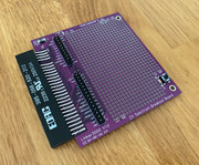
It has all the address and data lines in order, so i think it will be a bit easier to get it going, and very cheap too:
-
1024MAK
- Bugaboo
- Posts: 3123
- Joined: Wed Nov 15, 2017 2:52 pm
- Location: Sunny Somerset in the U.K. in Europe
Re: Spectrum Diagrom for 27C64 eprom, 8Kb, diy?
Yes, you can put a switch in. However, the same switch must also control the external ROM/EPROM/EEPROM.
Hence:
Put the switch to the external ROM in line with the /CE (/CS) pin. In the disabled position, it should connect the /CE (/CS) pin to +5V.
Also note that is the switch is operated while the computer is powered up, it will crash…
Mark
Hence:
- Switch in position 1, internal ROM enabled, external ROM disabled.
- Switch in position 2, internal ROM disabled, external ROM enabled.
Put the switch to the external ROM in line with the /CE (/CS) pin. In the disabled position, it should connect the /CE (/CS) pin to +5V.
Also note that is the switch is operated while the computer is powered up, it will crash…
Mark
“There are four lights!”
Step up to red alert. Sir, are you absolutely sure? It does mean changing the bulb
Looking forward to summer later in the year.
Re: Spectrum Diagrom for 27C64 eprom, 8Kb, diy?
Great! Thanks again!
Re: Spectrum Diagrom for 27C64 eprom, 8Kb, diy?
More dumd questions!
I found a 32Kb EEprom (28C256), but how do i burn a 8Kb, or 16Kb rom image into that EEprom?
Do you just start burning the image from the start of the EEprom, and leave the rest unprogrammed?
I found a 32Kb EEprom (28C256), but how do i burn a 8Kb, or 16Kb rom image into that EEprom?
Do you just start burning the image from the start of the EEprom, and leave the rest unprogrammed?
-
1024MAK
- Bugaboo
- Posts: 3123
- Joined: Wed Nov 15, 2017 2:52 pm
- Location: Sunny Somerset in the U.K. in Europe
Re: Spectrum Diagrom for 27C64 eprom, 8Kb, diy?
Yes, the code should start at the beginning of the EPROM or EEPROM chip (from address 0 as far as the chip and programmer are concerned).
Yes, any good programmer should be able to only program the range of addresses you want.
Alternatively, pad the file with as many bytes of 0xFF as needed.
Both EPROM and EEPROM has a value of 0xFF in the un-programmed state, so a programmer will skip any locations that have a value of 0xFF, vastly speeding up the programming operation.
Please note that the pin-out of some EEPROMs (such as a 28C256) is slightly different compared to 27 series EPROM chips.
In the ZX Spectrum, the /WRITE control pin needs to be logic high.
Mark
“There are four lights!”
Step up to red alert. Sir, are you absolutely sure? It does mean changing the bulb
Looking forward to summer later in the year.
Re: Spectrum Diagrom for 27C64 eprom, 8Kb, diy?
Make sure you don't leave unused address pins floating.
Another option is to duplicate ROM image (8KB 4 times or 16KB 2 times) and burn it to fill entire EEPROM.
Another option is to duplicate ROM image (8KB 4 times or 16KB 2 times) and burn it to fill entire EEPROM.
Re: Spectrum Diagrom for 27C64 eprom, 8Kb, diy?
Thnks Mark and zx64! Great help for me to learn these things!
Re: Spectrum Diagrom for 27C64 eprom, 8Kb, diy?
If i get this Diagrom thing up and running, can it be used in a Spectrum if the lower ram is not working?
-
1024MAK
- Bugaboo
- Posts: 3123
- Joined: Wed Nov 15, 2017 2:52 pm
- Location: Sunny Somerset in the U.K. in Europe
Re: Spectrum Diagrom for 27C64 eprom, 8Kb, diy?
Yes!
That’s the primary purpose of a ROM based diagnostic program, it can run without their being any working RAM.
Mark
That’s the primary purpose of a ROM based diagnostic program, it can run without their being any working RAM.
Mark
“There are four lights!”
Step up to red alert. Sir, are you absolutely sure? It does mean changing the bulb
Looking forward to summer later in the year.
Re: Spectrum Diagrom for 27C64 eprom, 8Kb, diy?
Thanks! Then i must get a diagrom up and running on my Spectrum! 
-
1024MAK
- Bugaboo
- Posts: 3123
- Joined: Wed Nov 15, 2017 2:52 pm
- Location: Sunny Somerset in the U.K. in Europe
Re: Spectrum Diagrom for 27C64 eprom, 8Kb, diy?
Note however that when I say a “ROM based diagnostic program”, I’m meaning one that has been designed to perform a RAM test without any working RAM. Not all system test ROMs will do this, as some are designed only to confirm that the Spectrum is actually working.
Mark
Mark
“There are four lights!”
Step up to red alert. Sir, are you absolutely sure? It does mean changing the bulb
Looking forward to summer later in the year.