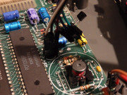
If you don’t have a current limited supply for the +12V, you could use any regulated PSU, but wire a 100 ohm resistor between the +12V output of the PSU and the +12V rail on the ZX Spectrum +2. Then you can measure the voltage across this 100 ohm resistor. The resistor will also limit the current if there is a short circuit (it will get hot in this case).
Voltage (U) in volts (V) divided by resistance (R) in ohms gives the current (I) in Amps (A)
So if you get 2.5V...
Code: Select all
U       2.5V
— = I = ———— = 0.025A = 25mA
R       100
There are other ways of working out where short circuits are, but in practice, on printed circuit boards, most are impractical. In order to measure current using a multimeter, the meter needs to be connected in series, so the current flows through it. This means breaking one of the conductors of the circuit you want to test.
The only other ways (without disturbing the PCB air the components) are to supply the circuit with power and either use a very sensitive voltmeter to compare the chip pin voltages with a known good unit. Or use an expensive IR camera to detect components that are warmer than they should be.
Mark