Hi all, I have one of the DCP Interspec BUS Expansion adaptors. It provides I/O functionality for the spectrum. You can read all about it here:
https://spectrumcomputing.co.uk/zxsr.php?id=1000195
I used to use this to control Meccano models - switching motors and lights on and detecting switch sensors etc. Pretty basic stuff really.
Since retiring, I started building Meccano models again and would, again, like to use the Interspec to control them. Sadly, I have mislaid the instruction sheet that came with it, giving the BASIC and PEEK and POKE codes that allowed me to control them. Also sadly, the cassette with the programs I wrote back then had gone walkabout.
So, does anyone possibly have any instructions for these expansion boards, maybe a photocopy (remember those?) of the instructions or perhaps a link to download them. I've tried searching, which is how I ended up here.
Any help and advice gratefully received.
Thanks
Chas.
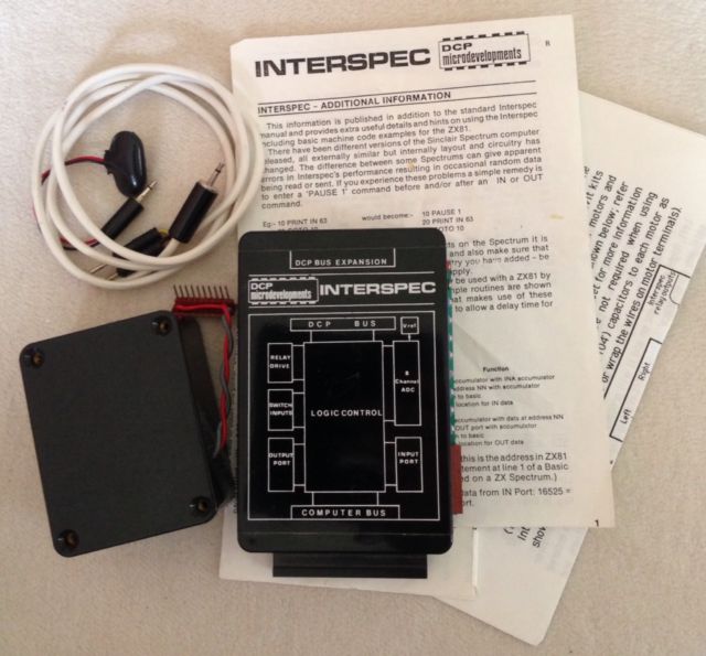
DCP Interspec BUS Expansion Adaptor
DCP Interspec BUS Expansion Adaptor
There are only 10 types of people in the world – those who understand binary, and those who don’t. 
Re: DCP Interspec BUS Expansion Adaptor
Found a pic of the interface and instruction sheet.
There are only 10 types of people in the world – those who understand binary, and those who don’t.
Re: DCP Interspec BUS Expansion Adaptor
There's a promo leaflet for the DCP devices here: https://forum.tlienhard.com/phpBB3/down ... da0fa45324
One of the pages indicates the TTL port is at IN/OUT 95, the ADC is IN 31, Switch inputs at IN 63 and relay outputs at OUT63. You may be able to figure out which ports map to which bits using a few basic IN/OUT commands and a multimeter.
One of the pages indicates the TTL port is at IN/OUT 95, the ADC is IN 31, Switch inputs at IN 63 and relay outputs at OUT63. You may be able to figure out which ports map to which bits using a few basic IN/OUT commands and a multimeter.
Re: DCP Interspec BUS Expansion Adaptor
And take a look at an old issue of ZX computing http://www.retro8bitcomputers.co.uk/Mag ... g&issue=14. Page 72 gives a review of the device along with a few basic programming examples.

Re: DCP Interspec BUS Expansion Adaptor
Such a cool piece of equipment, the idea of being able to control something really appeals. I hope you get it up and running. I’ve long wanted to do a similar thing, maybe one day I’ll get around to it.

Re: DCP Interspec BUS Expansion Adaptor
This is relevant to my interests so I'll be watching this thread with interest. I want to be able to do some simple home automation tasks, log temperatures etc. Does anyone know if there is any hardware documentation for this device? I'd love a circuit diagram to see how they did it.
I don't suppose you fancy taking the cover off and taking photos of the internals? If I knew what chips were used and had photos of the tracks I could possibly use that to draw one. It may also give us an idea of what commands would do what.
I don't suppose you fancy taking the cover off and taking photos of the internals? If I knew what chips were used and had photos of the tracks I could possibly use that to draw one. It may also give us an idea of what commands would do what.
Re: DCP Interspec BUS Expansion Adaptor
The output port could also be used for audio. Thanks to one of our Swedish friends we have fairly decent quality audio on the ZX81, streamed from an SD card on the ZXpand device. I'm sure this could be adapted to Speccy use.
A small recording tapped out of the Zeddy. It's RAW file mono 22109hz 8-bit when used on the Zeddy but thanks to Audacity and some compression surprisingly good especially when played on decent kit as opposed to laptop speakers etc. the top end should be tamed a bit and headphones will reveal its 8 bit origins but when put through something better like say a 2 satellite and sub-woofer system not too shabby.
Hmmm scrap that as I've just realised attachments aren't allowed, ah well never mind.
Re: DCP Interspec BUS Expansion Adaptor
Thanks for that link KiWi.Kiwi wrote: ↑Mon Jan 15, 2024 10:53 pm There's a promo leaflet for the DCP devices here: https://forum.tlienhard.com/phpBB3/down ... da0fa45324
One of the pages indicates the TTL port is at IN/OUT 95, the ADC is IN 31, Switch inputs at IN 63 and relay outputs at OUT63. You may be able to figure out which ports map to which bits using a few basic IN/OUT commands and a multimeter.
There are only 10 types of people in the world – those who understand binary, and those who don’t.
Re: DCP Interspec BUS Expansion Adaptor
Thanks for that too, very usefulKiwi wrote: ↑Mon Jan 15, 2024 11:02 pm And take a look at an old issue of ZX computing http://www.retro8bitcomputers.co.uk/Mag ... g&issue=14. Page 72 gives a review of the device along with a few basic programming examples.
There are only 10 types of people in the world – those who understand binary, and those who don’t.
Re: DCP Interspec BUS Expansion Adaptor
I'm sure I will, somewhere in the boxes from my move 20+ years ago, the instructions are still there - I'm a bit of a hoarder so I would never have thrown that out. Watch this space.
There are only 10 types of people in the world – those who understand binary, and those who don’t.
Re: DCP Interspec BUS Expansion Adaptor
Yes, I will do that, as I need to check that it's not been damaged whilst in storage - mould, water etc. Watch this space.Namtip wrote: ↑Tue Jan 16, 2024 11:05 am This is relevant to my interests so I'll be watching this thread with interest. I want to be able to do some simple home automation tasks, log temperatures etc. Does anyone know if there is any hardware documentation for this device? I'd love a circuit diagram to see how they did it.
I don't suppose you fancy taking the cover off and taking photos of the internals? If I knew what chips were used and had photos of the tracks I could possibly use that to draw one. It may also give us an idea of what commands would do what.
There are only 10 types of people in the world – those who understand binary, and those who don’t.
Re: DCP Interspec BUS Expansion Adaptor
UPDATE:
Thanks to that document via kiwi, I have begun basic testing of the module - IT WORKS!
I managed to find a reference to the original documentation and I have now been sent a scanned copy. I'm in the process of OCRing it and will create a WORD / PDF version of it which I will share.
I'm also putting together a video on testing and using the module, I'll share that on YouTube.
Continue watching this space
There are only 10 types of people in the world – those who understand binary, and those who don’t.
Re: DCP Interspec BUS Expansion Adaptor
OK, just spent many hours OCRing, editing and remaking the user guide. I've created a page about the INTERSPEC on my website so you can download a PDF version there.
I'll be building a test rig and programs to test it with and putting my results there. Hope this helps more INTERSPEC users.
https://cil-electronics.co.uk/retro-com ... -interspec
I also plan to create a circuit diagram of the INTERSPEC using KiCad based on the internal photos of the unit I've taken.
There are only 10 types of people in the world – those who understand binary, and those who don’t.
Re: DCP Interspec BUS Expansion Adaptor
I want to know what sort of Meccano models you controlled! I was at a Meccano guild meeting this afternoon and it was disappointingly lacking in wonky old computer interfaces 
Many years ago I built a relay driver interface for my BBC micro, which I used to computerise a Meccano gantry crane. I showed it at the annual exhibition in Skegness but sadly I'm not sure any photographs exist, as that was still back in the days you had to waste film on photographing your models
Many years ago I built a relay driver interface for my BBC micro, which I used to computerise a Meccano gantry crane. I showed it at the annual exhibition in Skegness but sadly I'm not sure any photographs exist, as that was still back in the days you had to waste film on photographing your models
Re: DCP Interspec BUS Expansion Adaptor
I've just uploaded the video to my YT channel, you can view it here:
Hope you find it useful
Hope you find it useful
There are only 10 types of people in the world – those who understand binary, and those who don’t.
Re: DCP Interspec BUS Expansion Adaptor
Really pleased the magazine article was of some use to get started. Brilliant to see the OCR copy of the full manual.
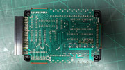
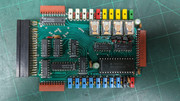
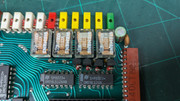
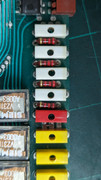
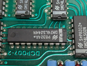
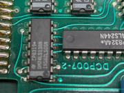
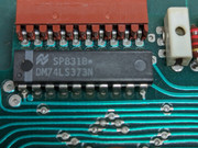
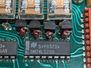
I'm with @Namtip on the photos. If you have chance to take some photos of the PCB, it would be good to see if we can reverse engineer it. The magazine articles mention a board with 10 ICs and the manual gives an idea of what they are for certain ports but there's nothing like seeing the actual unit!
I'm with @Namtip on the photos. If you have chance to take some photos of the PCB, it would be good to see if we can reverse engineer it. The magazine articles mention a board with 10 ICs and the manual gives an idea of what they are for certain ports but there's nothing like seeing the actual unit!
Re: DCP Interspec BUS Expansion Adaptor
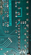
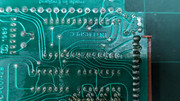
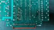
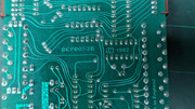
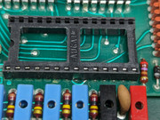
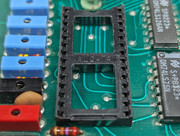
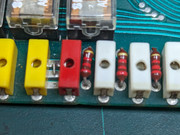
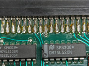
Here's some photos of the PCB and chips. I'm working on a reverse engineering diagram too. Hope they help you.


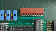


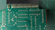
There are only 10 types of people in the world – those who understand binary, and those who don’t.
Re: DCP Interspec BUS Expansion Adaptor
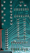
Thanks for the all photos - they're really useful.
I've created a first cut of a schematic https://github.com/ZXQuirkafleeg/ZX-Int ... 20v0.1.pdf. It's based your photos but there are a few gaps:
1) Diode types, cap values and tx types are all estimates. It would be good to get the proper values - though I expect anything reasonable will work.
2) I'm assuming ADC pin 16 Vref (-ve) is at ground but can't make out for certain.
3) Address decoder logic (2 * LS02 & LS138) is an estimate based on the tracks I can see and datasheets for the latches etc. I think it's right but it would be good to confirm.
4) I suspect LS93 is used as a /4 counter to generate the ADC clock from the spectrum CPU clock. Can't be sure as the tracks are hidden but the ADC requires a clock between 10KHz-1.28MHz. The spectrum CPU clock is fed into the LS93 via a LS20 NAND gate but the other pins of the gate are connected to the RC network above the LS20 and LS93 on the PCB. I'm not sure what's going on here but if you find out where the track between pins 10&11 of LS93 (and 4&5 of LS20) it might shed a bit of light.
The unit looks useful - I may well try to build one once there's a reasonable schematic!
Re: DCP Interspec BUS Expansion Adaptor
Hi Kiwi,
Thanks for that. I'll take it to bits and see if I can help resolve the questions, certainly with the component types and values.
Thanks for that. I'll take it to bits and see if I can help resolve the questions, certainly with the component types and values.
Kiwi wrote: ↑Sat Jan 27, 2024 6:26 pm Thanks for the all photos - they're really useful.
I've created a first cut of a schematic https://github.com/ZXQuirkafleeg/ZX-Int ... 20v0.1.pdf. It's based your photos but there are a few gaps:
1) Diode types, cap values and tx types are all estimates. It would be good to get the proper values - though I expect anything reasonable will work.
2) I'm assuming ADC pin 16 Vref (-ve) is at ground but can't make out for certain.
3) Address decoder logic (2 * LS02 & LS138) is an estimate based on the tracks I can see and datasheets for the latches etc. I think it's right but it would be good to confirm.
4) I suspect LS93 is used as a /4 counter to generate the ADC clock from the spectrum CPU clock. Can't be sure as the tracks are hidden but the ADC requires a clock between 10KHz-1.28MHz. The spectrum CPU clock is fed into the LS93 via a LS20 NAND gate but the other pins of the gate are connected to the RC network above the LS20 and LS93 on the PCB. I'm not sure what's going on here but if you find out where the track between pins 10&11 of LS93 (and 4&5 of LS20) it might shed a bit of light.
The unit looks useful - I may well try to build one once there's a reasonable schematic!
There are only 10 types of people in the world – those who understand binary, and those who don’t.
Re: DCP Interspec BUS Expansion Adaptor
You seem to be just a few years too late. www.dcpmicro.com takes me to a new standard getting started Wordpress page, that does contain in the lower left corner:
Using the wayback machine https://web.archive.org/web/20230128190 ... /index.htm shows that until their closure you would still have been able to order new units and a set of manualsDCP Microdevelopments
A record of the developments and products produced by DCP Microdevelopments from its inception in 1981 until closure through retirement in 2022.
Re: DCP Interspec BUS Expansion Adaptor
TOO LATE? - er that's why they call it RETRO COMPUTING nowadaysStefan wrote: ↑Sun Jan 28, 2024 8:39 am You seem to be just a few years too late. www.dcpmicro.com takes me to a new standard getting started Wordpress page, that does contain in the lower left corner:
Yep, been there. Still if Kiwi's schematics work out, we can recreate a new INTERSPEC?Stefan wrote: ↑Sun Jan 28, 2024 8:39 am Using the wayback machine https://web.archive.org/web/20230128190 ... /index.htm shows that until their closure you would still have been able to order new units and a set of manuals
There are only 10 types of people in the world – those who understand binary, and those who don’t.
Re: DCP Interspec BUS Expansion Adaptor
My point was more my surprise at finding that until two years ago the original producer was still trading and selling these.
Re: DCP Interspec BUS Expansion Adaptor
Ah, Yes, I see now, sorry, no offence meant, just didn't spot the date. Wow, if only I had cleared the loft a couple of years earlier...
There are only 10 types of people in the world – those who understand binary, and those who don’t.
Re: DCP Interspec BUS Expansion Adaptor
Thanks Kiwi, a great start, you're obviously well used to using that software. Hopefully this may help with the gaps.Kiwi wrote: ↑Sat Jan 27, 2024 6:26 pm Thanks for the all photos - they're really useful.
I've created a first cut of a schematic https://github.com/ZXQuirkafleeg/ZX-Int ... 20v0.1.pdf. It's based your photos but there are a few gaps:
1) Diode types, cap values and tx types are all estimates. It would be good to get the proper values - though I expect anything reasonable will work.
2) I'm assuming ADC pin 16 Vref (-ve) is at ground but can't make out for certain.
3) Address decoder logic (2 * LS02 & LS138) is an estimate based on the tracks I can see and datasheets for the latches etc. I think it's right but it would be good to confirm.
4) I suspect LS93 is used as a /4 counter to generate the ADC clock from the spectrum CPU clock. Can't be sure as the tracks are hidden but the ADC requires a clock between 10KHz-1.28MHz. The spectrum CPU clock is fed into the LS93 via a LS20 NAND gate but the other pins of the gate are connected to the RC network above the LS20 and LS93 on the PCB. I'm not sure what's going on here but if you find out where the track between pins 10&11 of LS93 (and 4&5 of LS20) it might shed a bit of light.
The unit looks useful - I may well try to build one once there's a reasonable schematic!
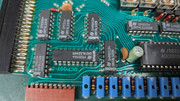
1. The diodes across the relays are unlabelled, just yellow-brown-yellow stripes. I would guess at 1N4148 types.
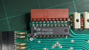
2. Pin 16 of the ADC is indeed ground.
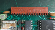
3. Can't confirm but have taken some more close-ups of the board to show better the tracks. Let me know if there is a specific pin you are unsure of and I'll meter it out.
4. Have removed the ADC and photographed the board close up.
Pin 10 of the LS93 connects to pin 7 of the LS20, to pin 8 for the LS138, pin 10 of the LS244 and to the 3rd & 4th underside spectrum connector, next to the notch. Effectively 0V. Pin 11 of the LS93 does not connect to anything, no trace under the chip.
Pin 4 & 5 of the LS 20 is connected to one end of the 2K2 resistor, the other end of the resistor goes to 5V
The diode near the 5V connector of the Analogue input, is a 2.7V Zener, presumably the reference for the A/D Converter.
The transistors driving the relays are BC184L
Hope this helps, a schematic will be useful to me and others, should the unit ever go faulty.
Cheers
Chas
Here's the photos:


There are only 10 types of people in the world – those who understand binary, and those who don’t.
Re: DCP Interspec BUS Expansion Adaptor
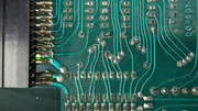
Hi, that's great - thanks again for the info and pics.
It looks like the NAND gate is simply used as a buffer for the CPU clock signal and the rest of the inputs are pulled up via the 2K2 resistor. The adjacent cap now looks like a decoupling cap.
Would you mind checking if pins 1 and 12 are connected on the LS93 ? And where the ADC clock i/p (pin 10) connects to on the LS93 ? It's probably pin 8 or 9 on the LS93. This should complete the clock gen cct.
I think all the ceramic caps are 47nf but would also mind checking and letting me know the values of the electrolytics ?