Making a Scalextric lap counter

For experts to discuss very technical stuff and newbies to ask why the Spectrum they bought off ebay doesn't work.
Post Reply
User avatar
Hedge1970
Manic Miner
Posts: 388
Joined: Mon Feb 18, 2019 2:41 pm

Making a Scalextric lap counter

Post by Hedge1970 »

I discovered the concept of a latch card a couple of years ago after asking about controlling robotic peripherals. The name was new to me, I discovered it along with a shopping list, albeit 40yrs old in Sinclair Projects magazine https://spectrumcomputing.co.uk/magazin ... r_Projects. I started buying a few bits but soon stopped after reading in the second release of Sinclair Projects that there was an error in the previous listing. This was enough to put me off, as I wanted to be 100% sure it would work before plugging in a peripheral I assembled to a 40yr old Spectrum.

Fast forward to this year and this post about DCP Interspec BUS Expansion Adaptor - viewtopic.php?t=10851 by @ChasL001 . Once again my interest was peeked by the whole - control real world stuff from your Spectrum. So one morning I awoke early and started Googling, to my surprise I found there was a PCB board available on Sell My Retro that would do a similar job. The board was produced by Tynemouth Software and along with pictures of the bare PCB Tynemouth Software had included a shopping list of the components required to assemble it. Well I bought the board and bought the components and proceeded to solder the whole thing together.

There is another piece to this puzzle, Usborne Books. Now I can't remember if the book itself was recommended to me or if having been recommended to look at their "Learn Machine Code" books I stumbled across it, but there is a book online - I am not sure of the legitimacy of the book to download so I won't post the link - called "How to Make Computer Model Controllers for c64. VIC 20, Spectrum & BBC" by Usborne Books. It includes everything you need to build - amongst other things - a Scalextric Lap Counter. They highlight in the book that the ZX Spectrum has no physical input output ports and recommend you buy an interface card like the "DCP Interspec BUS Expansion Adaptor", they call them "Parallel Input Ouput interface boards".

Anyway back to my board, first step is to test the card I had assembled. Now I have a few 48k Spectrums some I think are bullet proof and can happily get used all day everyday for weeks at a time. Then there are others that are a bit flaky, tend to have issues after a few hours running. not sure why, perhaps dodgy solder joint or dry capacitors or failing xyz. Now the good systems use either Scart or HDMI graphics "cards" which are themselves peripherals. But... I choose not to plug my shaky handed self soldered expansion card into one of these expensive items :lol: So I chose a suitable candidate with composite Mod and with some trepidation I plugged in the card and switched on the Spectrum... Yay! no magic smoke from either the computer or the card and the Spectrum is still displaying its start up logo. Step one passed, cup of tea in order.

Step 2 was today I got to test the actual light sequence I wanted to use on my lap timing bridge to start the race. There are - from what I can see - 16 controlled output ports 8 on OUT 1 and 8 on OUT 3. I only need five. With a short program I can light each one then pause for a random time followed by "Lights Out" F1 style to start the race. Hopefully next week I will have the lap counting sensor circuit wired up and ready to test. but for now its just the output ports to test.

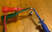
I am using a bread board to configure the circuit - I had never heard of let alone used a breadboard until this project so to any electronic experts out there apologies if its all wired up crooked!!

So the result

Image

Here is the board with a case I printed earlier for it

Image
User avatar
PeterJ
Site Admin
Posts: 6879
Joined: Thu Nov 09, 2017 7:19 pm
Location: Surrey, UK

Re: Making a Scalextric lap counter

Post by PeterJ »

Great little construction project @Hedge1970. Nice work!
User avatar
Hedge1970
Manic Miner
Posts: 388
Joined: Mon Feb 18, 2019 2:41 pm

Re: Making a Scalextric lap counter

Post by Hedge1970 »

PeterJ wrote: Fri Feb 09, 2024 5:26 pm Great little construction project @Hedge1970. Nice work!
Thanks Peter, I suspect I’d have had a different career had I discovered this when I originally got my spectrum.
User avatar
1024MAK
Bugaboo
Posts: 3123
Joined: Wed Nov 15, 2017 2:52 pm
Location: Sunny Somerset in the U.K. in Europe

Re: Making a Scalextric lap counter

Post by 1024MAK »

Well done 8-) :D :dance

Don't worry about the breadboard circuitry looking messy, more about that later...

I presume you mean this I/O board from Tynemouth Software on the Sell My Retro site?

Tynemouth Software made a blog post about this I/O board here.

I also have one of these boards. I don't have a photo to hand, and don't have a case for it.

Back to breadboards, I use them (I have many) for temporary and experimental circuits. If you are a really tidy person, it is possible to create neat layouts of components. But I'm not one of those people. Hence my creations are often a bit, err, untidy. For example, this breadboard (which has bits of various circuits on it):


There are some other examples on my YouTube channel.

Oh, a note for others, who only need digital inputs. Some Kempston (including clines/compatible) and all Sinclair Interface 2 joystick interfaces can be used. Each port has five digital TTL inputs. Note that the +2 grey joystick ports can also be used, but not the joystick ports on a +2A, +2B, +3 or a +3B.

Mark
Last edited by 1024MAK on Sat Feb 10, 2024 4:26 pm, edited 1 time in total.
:!: Standby alert :!:
“There are four lights!”
Step up to red alert. Sir, are you absolutely sure? It does mean changing the bulb :dance
Looking forward to summer later in the year.
User avatar
Hedge1970
Manic Miner
Posts: 388
Joined: Mon Feb 18, 2019 2:41 pm

Re: Making a Scalextric lap counter

Post by Hedge1970 »

1024MAK wrote: Sat Feb 10, 2024 2:34 pm I presume you mean this I/O board from Tynemouth Software on the Sell My Retro site?

Tynemouth Software made a blog post about this I/O board here.
Ahhh that’s it… I must have found the blog first then bought the board. Of course that’s where the book came from as well. Thank you Mark.

I will take a look at your YouTube vids on breadboards, I am waiting for some vero boards to arrive so I can do the lap counter circuit but I might just see if I can do it on the breadboard first.
User avatar
Hedge1970
Manic Miner
Posts: 388
Joined: Mon Feb 18, 2019 2:41 pm

Help understanding Transistor leg layout

Post by Hedge1970 »

Beginner Alert !!!! I am a bit confused by the book, and wonder of someone experienced with circuits can help - or confirm there is an inconsistency in the book. The book shows a Transistor BC108 mounted in the circuit yet the names of the legs in the book don't seem to correlate to the Farnell Datasheet here ->https://www.farnell.com/datasheets/296633.pdf <-

I assume (and perhaps this is the problem) the orientation of the picture shown in the datasheet (summarised below) is from the bottom of the transistor rather than looking down on top of it. If so the datasheet shows the leg by the Metal Tab is the Emitter then going clockwise around the transistor is the Base and finally the Collector. which seems ok until you put the transistor the right way up when it becomes Emitter, Collector then Base.

Yet the book itself calls for the Emitter, then clockwise Base and Collector - again summarised below.

Summary
Image

The actual circuit is shown below, I wonder if anyone with the relevant experience can tell if its correct or not given what a Transistor should do?

Circuit
Image

Finally below is a picture of the transistor itself

Image

I used this video to attempt to identify the legs and again it confirmed what the Farnell spec sheet said Base is both Positive and next to the tab (which I also believe confirms this to be a NPN transistor). The next leg I tested I got 6.83 voltage drop and then the final leg gave a voltage drop of 6.80 according to the vid the lower drop is the Collector so this gives Emitter Collector and Base in a clockwise direction

User avatar
1024MAK
Bugaboo
Posts: 3123
Joined: Wed Nov 15, 2017 2:52 pm
Location: Sunny Somerset in the U.K. in Europe

Re: Making a Scalextric lap counter

Post by 1024MAK »

Transistor lead outs are always viewed from below unless stated otherwise (this is opposite to IC/chip pin outs which are viewed from above).

Yes, a BC108 is a NPN. And yes the emitter is the lead next to the tab. The middle lead is the base, leaving the remaining lead as the collector.

The data-sheet is correct. The illustration from the book is misleading.

When using a diode tester, with a positive voltage (red meter probe/lead) connected to the base, you should get a 0.5V to 0.65V to the emitter, or to the collector. All other combinations should show over range (OL) or open circuit.

The circuit is using a resistor and the LDR as a potential divider. This then controls the transistor, which in turn controls the trigger pin of the NE555 timer chip.

The NE555 timer chip is configured as a monostable.

Mark
:!: Standby alert :!:
“There are four lights!”
Step up to red alert. Sir, are you absolutely sure? It does mean changing the bulb :dance
Looking forward to summer later in the year.
User avatar
Hedge1970
Manic Miner
Posts: 388
Joined: Mon Feb 18, 2019 2:41 pm

Re: Making a Scalextric lap counter

Post by Hedge1970 »

Thank you Mark,

So with the base being positive does that mean it is attached to the 1k resistor above it that currently shows the collector?
User avatar
1024MAK
Bugaboo
Posts: 3123
Joined: Wed Nov 15, 2017 2:52 pm
Location: Sunny Somerset in the U.K. in Europe

Re: Making a Scalextric lap counter

Post by 1024MAK »

Don't confuse the diode like effects when testing a bipolar transistor like a BC108 with how it actually works when used in an amplifier or switching circuit. The transistors operation is far more complex.

In this circuit, the transistor is used as a common emitter amplifier.

The 100kΩ potentiometer (variable resistor) sets the bias current to both the transistor base and forms the voltage divider in combination with the LDR. LDR means Light Dependent Resistor. As the level of light falling on the LDR varies, so does its resistance. And in turn, the DC voltage at the junction between these components also varies. The 1kΩ resistor connected to the base terminal limits the maximum current that can flow into the base terminal of the transistor.

With a NPN transistor like a BC108, the current flowing from the collector to the emitter depends on the current flowing from the base to the emitter. One of the characteristics of a transistor is the gain (also known as the hFE). A BC108 typically may gave a gain of between 100 and 450. Also important, is that in order to work (switch on), in this circuit, the base voltage must be around 0.55V or greater than the voltage at the emitter. When fully switched on, the voltage between the collector and the emitter will be very low, typically less than 0.25V in this circuit design.

If we use easy numbers and assume that the gain is 100, a current of only 50µA (0.05mA) flowing into the base will be amplified by 100 times, and hence the current flowing from the collector to the emitter will be 5mA.

The transistor and the 1kΩ resistor connected to the collector terminal act as another voltage divider. This 1kΩ resistor limits the current that can flow to a maximum of 5mA (5V divided by 1000Ω gives a current of 5mA). Hence setting the limits that this part of the circuit can operate between. Because the current can vary, the voltage can move between about 5V and 0.25V. This is applied to pin 2 (the trigger input) of the NE555 timer chip. When the voltage at this pin drops below ⅓ of the supply voltage to the chip (so if the supply is 5V, the trigger pin voltage threshold is about 1.66V), the chip will start a timing cycle.

Mark
Last edited by 1024MAK on Mon Feb 12, 2024 8:35 pm, edited 2 times in total.
:!: Standby alert :!:
“There are four lights!”
Step up to red alert. Sir, are you absolutely sure? It does mean changing the bulb :dance
Looking forward to summer later in the year.
User avatar
Hedge1970
Manic Miner
Posts: 388
Joined: Mon Feb 18, 2019 2:41 pm

Re: Making a Scalextric lap counter

Post by Hedge1970 »

Thanks again Mark, I’ll sit down with a cup of tea and go through all that, at a high level it makes sense. I am waiting on the resistors to arrive so have at least a few hours tomorrow morning before my postie arrives - although I suspect Wednesday is more likely.
User avatar
1024MAK
Bugaboo
Posts: 3123
Joined: Wed Nov 15, 2017 2:52 pm
Location: Sunny Somerset in the U.K. in Europe

Re: Making a Scalextric lap counter

Post by 1024MAK »

Here's a circuit simulation.

Because it does not include a potentiometer, I've used a fixed resistor. Also not included is a LDR, so I have used a clickable logic level input (swaps between L and H) a diode and a fixed resistor. This very crudly simulates day/night as if there was a LDR.

https://www.falstad.com/circuit/circuit ... CB4TJQ+wgA

Mark
:!: Standby alert :!:
“There are four lights!”
Step up to red alert. Sir, are you absolutely sure? It does mean changing the bulb :dance
Looking forward to summer later in the year.
User avatar
Hedge1970
Manic Miner
Posts: 388
Joined: Mon Feb 18, 2019 2:41 pm

Re: Making a Scalextric lap counter

Post by Hedge1970 »

Thanks Mark,

I had a good look and it really helps to have as a reference point. It helped me realise that my previous post was not very clear. The problem I have with the transistor, if you look at the farnell data sheet go clockwise from the emitter and the next leg is the collector whereas on your circuit the next leg is the base. This is where I am confused as that's the same problem with the book.

I must be reading it all wrong. where it shows the emitter by the tab on the datasheet vs the book that shows the tab by the collector - this is whats confusing.
User avatar
1024MAK
Bugaboo
Posts: 3123
Joined: Wed Nov 15, 2017 2:52 pm
Location: Sunny Somerset in the U.K. in Europe

Re: Making a Scalextric lap counter

Post by 1024MAK »

I'll get a real one out later and take a photo.

Mark
:!: Standby alert :!:
“There are four lights!”
Step up to red alert. Sir, are you absolutely sure? It does mean changing the bulb :dance
Looking forward to summer later in the year.
User avatar
Hedge1970
Manic Miner
Posts: 388
Joined: Mon Feb 18, 2019 2:41 pm

Re: Making a Scalextric lap counter

Post by Hedge1970 »

1024MAK wrote: Tue Feb 13, 2024 4:30 pm I'll get a real one out later and take a photo.

Mark
Thanks Mark, I believe using my multimeter I can identify the base so I will just use that as the reference point and hope for the best.
User avatar
1024MAK
Bugaboo
Posts: 3123
Joined: Wed Nov 15, 2017 2:52 pm
Location: Sunny Somerset in the U.K. in Europe

Re: Making a Scalextric lap counter

Post by 1024MAK »

Hedge1970 wrote: Tue Feb 13, 2024 4:36 pm Thanks Mark, I believe using my multimeter I can identify the base so I will just use that as the reference point and hope for the best.
Oh no, you don't get off that easy....


Image

Image

Image

Image

Image

Image

Image

Image

Mark
:!: Standby alert :!:
“There are four lights!”
Step up to red alert. Sir, are you absolutely sure? It does mean changing the bulb :dance
Looking forward to summer later in the year.
User avatar
Hedge1970
Manic Miner
Posts: 388
Joined: Mon Feb 18, 2019 2:41 pm

Re: Making a Scalextric lap counter

Post by Hedge1970 »

That’s so much good info. Above and beyond Mark but thank you so much. Now all the bits have arrived, I am going to take it slow but hope to have something together by tomorrow.
User avatar
Hedge1970
Manic Miner
Posts: 388
Joined: Mon Feb 18, 2019 2:41 pm

Re: Making a Scalextric lap counter

Post by Hedge1970 »

Hey Mark, All working. :dance excuse my messy work bench!

The led lights shows the sensor being triggered, the board additionally sends approx 5v to an output pin which the Spectrum will pick up on via "IN 1". In the book I am working from, the original design for the trigger had the light sensor positioned horizontally pointing at the door of the car. Given that I need a light shining at the sensor to get it to work 100% I will build what we in the slotcar world call a light bridge. That is I will embed the light sensor in the track facing up and have a bridge with 5 bright leds shining down, as the car passes over the sensor it will cut the light source - like my hand does above. - triggering a lap.

Image

Thanks again
User avatar
Hedge1970
Manic Miner
Posts: 388
Joined: Mon Feb 18, 2019 2:41 pm

Re: Making a Scalextric lap counter

Post by Hedge1970 »

So I have taken this project as far as I intend for now. its been a real mark in the sand for me as I now know I can look to use my Spectrum for a whole host of other projects. I was really surprised at how the components in the books circuit diagrams can still be bought and used some 40 years later. Also while not relevant particularly for here, the hardware for the bridge can hook into an Arduino Uno so the whole project has relevance in 2024 as opposed to only working on the 1984 ZX Spectrum. I guess the standards for communication developed back then where good enough to still be useable today - or perhaps there is a simpler more logical solution that I am blissfully unaware of. Anyway here is a video that outlines what the project has achieved including a track test at the end where its compared to a known timing system. if you don't like videos (and I get it) in a couple of weeks if there is interest I'll do a forum post write up.

Mark, thank you for all your help.

User avatar
1024MAK
Bugaboo
Posts: 3123
Joined: Wed Nov 15, 2017 2:52 pm
Location: Sunny Somerset in the U.K. in Europe

Re: Making a Scalextric lap counter

Post by 1024MAK »

No problem, I like helping people.

You may want to check the video settings, it's currently not working, instead we see a "this video is private" message...

Mark
:!: Standby alert :!:
“There are four lights!”
Step up to red alert. Sir, are you absolutely sure? It does mean changing the bulb :dance
Looking forward to summer later in the year.
User avatar
Hedge1970
Manic Miner
Posts: 388
Joined: Mon Feb 18, 2019 2:41 pm

Re: Making a Scalextric lap counter

Post by Hedge1970 »

Ughh, school boy error, should be visible now.
User avatar
1024MAK
Bugaboo
Posts: 3123
Joined: Wed Nov 15, 2017 2:52 pm
Location: Sunny Somerset in the U.K. in Europe

Re: Making a Scalextric lap counter

Post by 1024MAK »

Yeah, it's now okay :D

Will watch it later.

Mark
:!: Standby alert :!:
“There are four lights!”
Step up to red alert. Sir, are you absolutely sure? It does mean changing the bulb :dance
Looking forward to summer later in the year.
Post Reply