Spectrum 48k - Issue 2 - Repairing

For experts to discuss very technical stuff and newbies to ask why the Spectrum they bought off ebay doesn't work.
User avatar
Bubu
Manic Miner
Posts: 542
Joined: Fri Apr 02, 2021 8:24 pm
Location: Spain

Spectrum 48k - Issue 2 - Repairing

Post by Bubu »

Jarl, torpedos!

Hi, all!

I've found into a box a Spectrum Issue 2 PCB, I can't remember where it comes from, or if I tried to repair by that moment, but it's at least 10 years I don't see this PCB. Anyway I've just plugged it and no image, no sound at all, it's dead!!

Here some pics:


Image


Image


At a first look, I can see these issues:

- No REG (regulator?)
- Low RAM is socketed, but some pads on the back side are fixed
- C44 is nulled

I've got logic probe and oscilloscope, soldering iron, etc.

Any advice? I think first I must try is the regulator.
If something works, don't touch it !!!! at all !!!
User avatar
spider
Dynamite Dan
Posts: 1099
Joined: Wed May 01, 2019 10:59 am
Location: Derby, UK
Contact:

Re: Spectrum 48k - Issue 2 - Repairing

Post by spider »

At least the RAM is all socketed !

Although the soldering standard does not look good (sorry not meaning to offend at all honestly) I think I can see some possibly shorts in it. It does not look beyond repair a wick or desolder pump will clean the worst up and it can be re-done without any trauma.

I suspect the wires are to fix broken or 'lifted' tracks but I'm not sure.

The regulator will need replacing, possibly with a standard 7x unit or a 'solid state' DC-DC one (better as no heatsink needed) standard reg will need heatsink.

It will be dead without a regulator. :)

The transistor sitting on the CPU is normal pretty sure my Issue2 + looks like that (that's broken too but in a different way!)

I'd not advise powering it up without the reg as I don't know if any current will reach the coil and then the ram chips, these chips don't seem to be happy if one of their voltages is absent.

Am sure the experts on here will appear at some point to provide more useful (than me) advice.
User avatar
Bubu
Manic Miner
Posts: 542
Joined: Fri Apr 02, 2021 8:24 pm
Location: Spain

Re: Spectrum 48k - Issue 2 - Repairing

Post by Bubu »

Thanx a lot for your answer! At least I'm not alone :D

Yes, first of all is to install a regulator. I'll do it with a TracoPower, as you well say, it doesn't need a heatsink. They are expensive, but I'm very happy with it in others Spectrum PCBs

Image
If something works, don't touch it !!!! at all !!!
User avatar
spider
Dynamite Dan
Posts: 1099
Joined: Wed May 01, 2019 10:59 am
Location: Derby, UK
Contact:

Re: Spectrum 48k - Issue 2 - Repairing

Post by spider »

Great :)

I'd say hold off powering up (even if the traco appeared now) until one of our tech experts on here perhaps adds something. Id' not want to say power it up and you find a missing supply to the ram and zap it etc, if memory serves if its missing the -5v the ram chips can be very unwell quickly.
User avatar
Bubu
Manic Miner
Posts: 542
Joined: Fri Apr 02, 2021 8:24 pm
Location: Spain

Re: Spectrum 48k - Issue 2 - Repairing

Post by Bubu »

Yes, sure, I'll wait for the experts, I don't want to see smoke from this PCB :D

Meanwhile, I can see that low RAM chips are M3764A-15, it means they're kind of 4164 type, and the pinout is this:


Image

So I really don't need -5V neither +12V...
If something works, don't touch it !!!! at all !!!
User avatar
1024MAK
Bugaboo
Posts: 3123
Joined: Wed Nov 15, 2017 2:52 pm
Location: Sunny Somerset in the U.K. in Europe

Re: Spectrum 48k - Issue 2 - Repairing

Post by 1024MAK »

It looks like all the DRAM was originally soldered. And all the original DRAM has been removed. The ‘lower’ DRAM chips been replaced with 64K bit DRAM chips that only need a single +5V supply. That may explain the changes near to capacitor C44.

Has the +12V supply to pin 8 of the ‘lower’ DRAM been isolated from the +12V supply? And instead been connected to the +5V supply?
Has the -5V supply to pin 1 of the ‘lower’ DRAM been isolated from the -5V supply?

It looks like the ‘upper’ DRAM chips are now 64K bit DRAM chips as well.

The Z80A looks like it’s been changed as well.

Mark
:!: Standby alert :!:
“There are four lights!”
Step up to red alert. Sir, are you absolutely sure? It does mean changing the bulb :dance
Looking forward to summer later in the year.
User avatar
Bubu
Manic Miner
Posts: 542
Joined: Fri Apr 02, 2021 8:24 pm
Location: Spain

Re: Spectrum 48k - Issue 2 - Repairing

Post by Bubu »

1024MAK wrote: Sun Aug 08, 2021 9:44 pm It looks like all the DRAM was originally soldered. And all the original DRAM has been removed. The ‘lower’ DRAM chips been replaced with 64K bit DRAM chips that only need a single +5V supply. That may explain the changes near to capacitor C44.
Right!! That's true!
1024MAK wrote: Sun Aug 08, 2021 9:44 pm Has the +12V supply to pin 8 of the ‘lower’ DRAM been isolated from the +12V supply? And instead been connected to the +5V supply?
Donno... Could I test "continuity" (is it so said?) between this pin and any +12V pin?


1024MAK wrote: Sun Aug 08, 2021 9:44 pm Has the -5V supply to pin 1 of the ‘lower’ DRAM been isolated from the -5V supply?
Yes, the pin 1 of the last DRAM chip is isolated from the circuit, so no pin 1 is feeded.
1024MAK wrote: Sun Aug 08, 2021 9:44 pm It looks like the ‘upper’ DRAM chips are now 64K bit DRAM chips as well.
Also changed? Didn't it come originallly with 4164 chips in upper RAM?
1024MAK wrote: Sun Aug 08, 2021 9:44 pm The Z80A looks like it’s been changed as well.
Yep, the Z80 looks new, very observant!
If something works, don't touch it !!!! at all !!!
User avatar
Bubu
Manic Miner
Posts: 542
Joined: Fri Apr 02, 2021 8:24 pm
Location: Spain

Re: Spectrum 48k - Issue 2 - Repairing

Post by Bubu »

Ah, there's also a bridge on the lower part of the PCB (I've marked it by a red line):


Image
If something works, don't touch it !!!! at all !!!
User avatar
Bubu
Manic Miner
Posts: 542
Joined: Fri Apr 02, 2021 8:24 pm
Location: Spain

Re: Spectrum 48k - Issue 2 - Repairing

Post by Bubu »

Not sure, but I think that bridge is for suplying +5V instead of +12V, to pins 8 of every DRAM. I'll be sure as soon as I get the Tracopower ;)
If something works, don't touch it !!!! at all !!!
User avatar
Bubu
Manic Miner
Posts: 542
Joined: Fri Apr 02, 2021 8:24 pm
Location: Spain

Re: Spectrum 48k - Issue 2 - Repairing

Post by Bubu »

OK, Tracos came, and I've got the Issue Two schematics:

Image

I'll check first of all if I can simply change the 7805 with the Traco or have to take in account something...
If something works, don't touch it !!!! at all !!!
User avatar
Bubu
Manic Miner
Posts: 542
Joined: Fri Apr 02, 2021 8:24 pm
Location: Spain

Re: Spectrum 48k - Issue 2 - Repairing

Post by Bubu »

Today I've replaced the 7805 by a TRACO:


Image


And now I've got +5.0V every where, but still no Video. How does video work? I remember that it needs +12V, so I think a TR is not working...
If something works, don't touch it !!!! at all !!!
User avatar
Bubu
Manic Miner
Posts: 542
Joined: Fri Apr 02, 2021 8:24 pm
Location: Spain

Re: Spectrum 48k - Issue 2 - Repairing

Post by Bubu »

Yessss, middle leg of TR5 is unsoldered, so no +12V is generated to the LM1889N:


Image
If something works, don't touch it !!!! at all !!!
User avatar
Bubu
Manic Miner
Posts: 542
Joined: Fri Apr 02, 2021 8:24 pm
Location: Spain

Re: Spectrum 48k - Issue 2 - Repairing

Post by Bubu »

TR5 solderd and... almost fixed!!!!


...almost :


Image


This Speccy works, boots, ROM runs the initial RAM test, and I've noted some strange issues:

- boot time is too short, as if this speccy was 16KB instead of 48KB
- screen botton shows a strange image. I think the problem is in the 3rd third. It blinks continously, but I can hardly read the (c) 1982 Sinclair Research Ltd message.
- I can write anything, and loud speaker works (bleep bleep bleep...)

I suspect of the ULA, and if it's so then this Speccy is no fixable (At least without having to sell my house to buy a ULA replacement)
If something works, don't touch it !!!! at all !!!
User avatar
spider
Dynamite Dan
Posts: 1099
Joined: Wed May 01, 2019 10:59 am
Location: Derby, UK
Contact:

Re: Spectrum 48k - Issue 2 - Repairing

Post by spider »

Does the keyboard respond properly then ?

Although you might have to type blind, try:

POKE 65535 , 100
PRINT PEEK 65535
POKE 65535 , 200
PRINT PEEK 65535

Does it display the 'new' value ? A 16K machine will not obviously :) I can't recall offhand what a 'real' 16K machine shows for the 'upper memory that is not there' , don't rely on emulation as Spin says its 0 and Spectaculator says its 255 (byte at 65535)

If the tape input works, I guess you could try to load a game or two, try a 16K one first maybe, then a 48K one. Perhaps older titles.
User avatar
Bubu
Manic Miner
Posts: 542
Joined: Fri Apr 02, 2021 8:24 pm
Location: Spain

Re: Spectrum 48k - Issue 2 - Repairing

Post by Bubu »

It's just that I have a problem: you can't see the letters with so many spots at the bottom, and I also don't have a keyboard. I did the test by short-circuiting a cable between KB1 and KB2. When I find a keyboard I will do that test, to see if I can enter the instructions blindly

Meanwhile the following occurs to me:

The screen addressing is 010TTSSS RRRCCCCC where T=third (00, 01 or 10)
So, if the spots are only on the 3rd third, then TT = 10, and it corresponds to A12. Then, I think I should check if that pin in the address bus is shorted or something.
If something works, don't touch it !!!! at all !!!
User avatar
spider
Dynamite Dan
Posts: 1099
Joined: Wed May 01, 2019 10:59 am
Location: Derby, UK
Contact:

Re: Spectrum 48k - Issue 2 - Repairing

Post by spider »

I was going to say you could always add line numbers to it so that way you only have to 'risk' one line at a time once you have a keyboard

Its probably quite easy to 'simulate' J then " twice and finally enter then try a tape or two though too, but I've not looked at that.
User avatar
Bubu
Manic Miner
Posts: 542
Joined: Fri Apr 02, 2021 8:24 pm
Location: Spain

Re: Spectrum 48k - Issue 2 - Repairing

Post by Bubu »

That's true, but I MUST get a keyboard... Yep, I've got a keyboard, but w/o the membrane... :(

I'm thinking of doing these tests:

- Type BORDER 1, so I can test the ULA (border and color)
- Plug a DivIDE, but I'm afraid it will smoke...
If something works, don't touch it !!!! at all !!!
User avatar
Bubu
Manic Miner
Posts: 542
Joined: Fri Apr 02, 2021 8:24 pm
Location: Spain

Re: Spectrum 48k - Issue 2 - Repairing

Post by Bubu »

DUPLICATE POST
Last edited by Bubu on Sun Aug 22, 2021 9:27 pm, edited 1 time in total.
If something works, don't touch it !!!! at all !!!
User avatar
Bubu
Manic Miner
Posts: 542
Joined: Fri Apr 02, 2021 8:24 pm
Location: Spain

Re: Spectrum 48k - Issue 2 - Repairing

Post by Bubu »

OK, next test, the divIDE:


Image

Image


The trash pixels are global, in the full image, but at least I know Z80, ROM and RAM are OK. There's no color instead. I keep on supecting the ULA.


Q: Is this ULA (ULA6C001E-5) the most compatible with an Issue two PCB?
If something works, don't touch it !!!! at all !!!
User avatar
Bubu
Manic Miner
Posts: 542
Joined: Fri Apr 02, 2021 8:24 pm
Location: Spain

Re: Spectrum 48k - Issue 2 - Repairing

Post by Bubu »

Meanwhile, I'll try to probe every pin on the ULA, this is the pinout:

Image
If something works, don't touch it !!!! at all !!!
User avatar
Bubu
Manic Miner
Posts: 542
Joined: Fri Apr 02, 2021 8:24 pm
Location: Spain

Re: Spectrum 48k - Issue 2 - Repairing

Post by Bubu »

Besides ULA, I think TR5 is wrong too, as I can't find 12V anywhere. VCC in LM1889 is 8V, not 12V, so it can be the faulty color reason.
I see that my TR5 is a BC308, so I think it's not the original one (ZTX213). In some sites I can read that a good replacement is a BC557. What about this, is BC308 = BC557 = ZTX213 ???


Thank you!!
If something works, don't touch it !!!! at all !!!
User avatar
Bubu
Manic Miner
Posts: 542
Joined: Fri Apr 02, 2021 8:24 pm
Location: Spain

Re: Spectrum 48k - Issue 2 - Repairing

Post by Bubu »

The daily news... :D


I've extracted TR5, that it was a BC308 and it wasn't generating the 12V at all. I've bought some BC557s, let's see what happens. If I get then 12V and image is still so trash, then I must give up cause I'll be sure it's an ULA faulty. But if I get 12V and image is repaired, then I'll... I'll... I'll promise I'll have 4 or 5 rum&cokes meanwhile playing the game you'll tell me :D :D :D
If something works, don't touch it !!!! at all !!!
User avatar
Bubu
Manic Miner
Posts: 542
Joined: Fri Apr 02, 2021 8:24 pm
Location: Spain

Re: Spectrum 48k - Issue 2 - Repairing

Post by Bubu »

I've just soldered a 3-pad (don't know if that's the right name of this) so I can insert or remove many times the TR5, as I know it's very usual it to be replaced:


Image


Now I take a new BC557 and check its health:


Image


It's time to put this TR into TR5 position:

Image


But no +12V anywhere. I don't understand at all... This is the DC/DC schema:


Image

Perhaps I must change C74 and possibly R60? Must I change TR4?


At this point, I need your help... :roll: :lol: :lol: :lol:
If something works, don't touch it !!!! at all !!!
zx64
Manic Miner
Posts: 211
Joined: Sat Jul 11, 2020 3:25 am
Location: Australia

Re: Spectrum 48k - Issue 2 - Repairing

Post by zx64 »

Check again if both transistors are good and inserted correctly (check pinout), everything else is much less likely to fail
User avatar
1024MAK
Bugaboo
Posts: 3123
Joined: Wed Nov 15, 2017 2:52 pm
Location: Sunny Somerset in the U.K. in Europe

Re: Spectrum 48k - Issue 2 - Repairing

Post by 1024MAK »

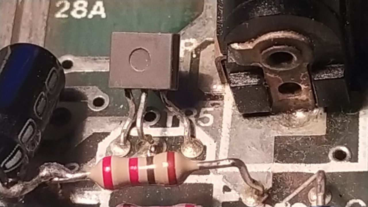
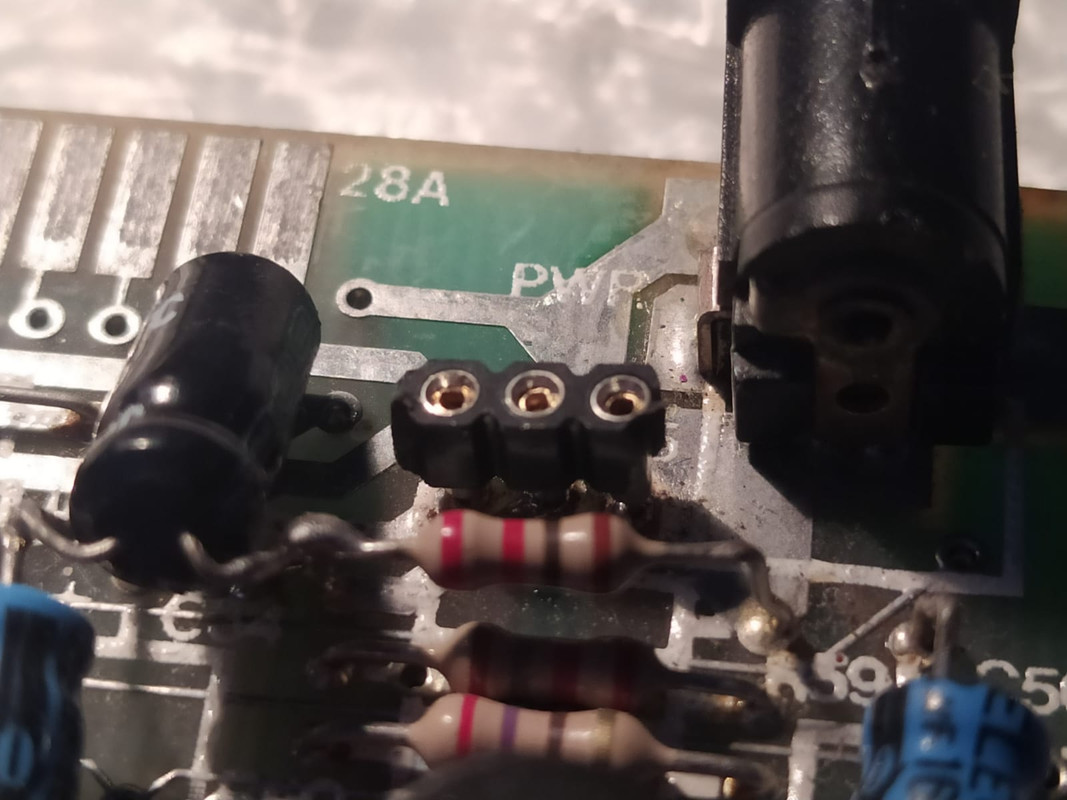
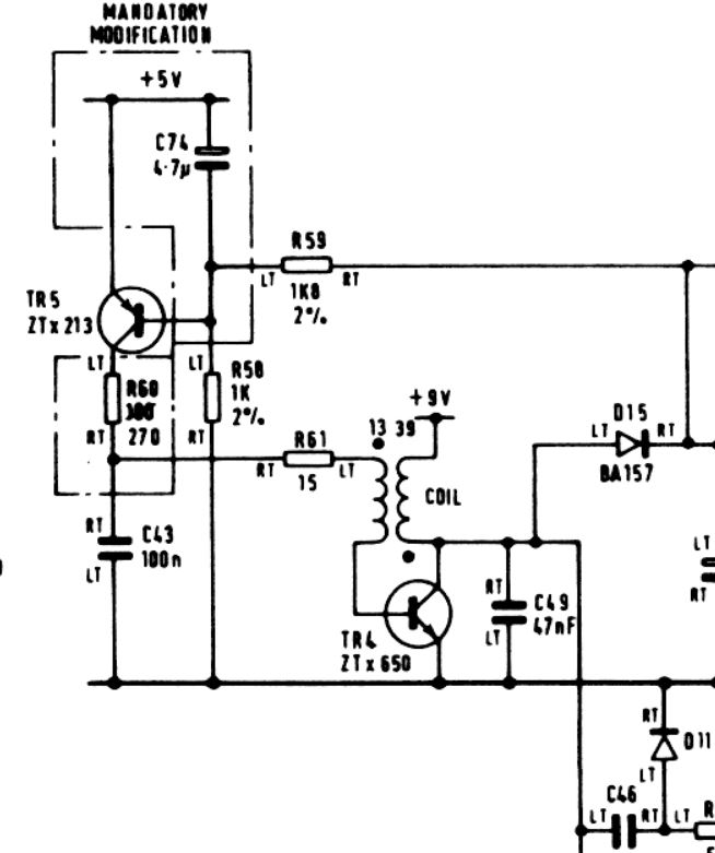
The +12V missing or being out of specification is due to a failure of the DC/DC converter circuitry. This is based on TR4, TR5, the ‘coil’ and the various associated resistors and capacitors.

The normal reason is due to TR4 having overheated and failed. On an issue two board where the DC/DC converter circuitry has not been modified to the latest Sinclair mod state, if TR4 is not oscillating, current can flow from the +9V (nominal) rail (that is, the 9V input) through the coil and appear on the +12V rail.

See my blog for details of the DC/DC converter modification.

There are typically five reasons that TR4 fails: edge-connector abuse (removal or fitting of an expansion while the computer is powered), incorrect 9V supply polarity, one or more of the 4116 (or equivalent) DRAM chips going faulty and drawing more current than normal, electrolytic capacitor failure or just a failure of the transistor on its own (especially if the wrong type is fitted).

TR5 acts as the error amplifier/reference comparator. It compares the voltage on the +12V rail (via the potential/voltage divider formed from R58 and R59) and compares it to the +5V (used as a reference voltage). If the +12V voltage is too low, it increases the drive current to TR4. If the +12V voltage is too high, it reduces the drive current to TR4.

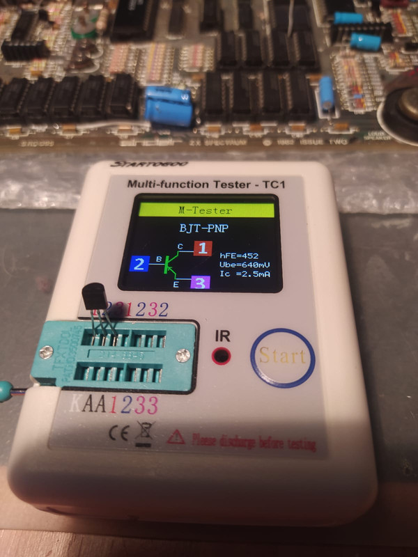
The type of transistor used for TR5 is not as critical as the type used for TR4. The ZTX213 is obsolete and hard to find. A BC307 or BC308 or BC557 can be used as replacements. As long as the different lead outs are taken into account. See here for a list of alternative components.

For TR4, I recommend fitting a ZTX651 or a ZXT653. Both are still available as new components.

Remove the existing transistor used in the TR4 position. Before fitting a replacement, test both the +12V supply and the -5V supply for a short circuit or abnormal low resistance. Test on the 20k, and then the 2k resistance range on your multimeter. Obviously with the board disconnected from the power. Do the test with the meter leads connected one way round, then again with the opposite polarity. Any resistance result less than about 800 ohms is suspicious.

Alternatively, as there is now no circuitry that needs the -5V supply, and you have replaced the 7805 with a DC/DC converter/switching regulator, you could instead bypass the Sinclair DC/DC converter circuitry and instead feed the board with a regulated +12V DC supply. Please ask for details if you are not sure.

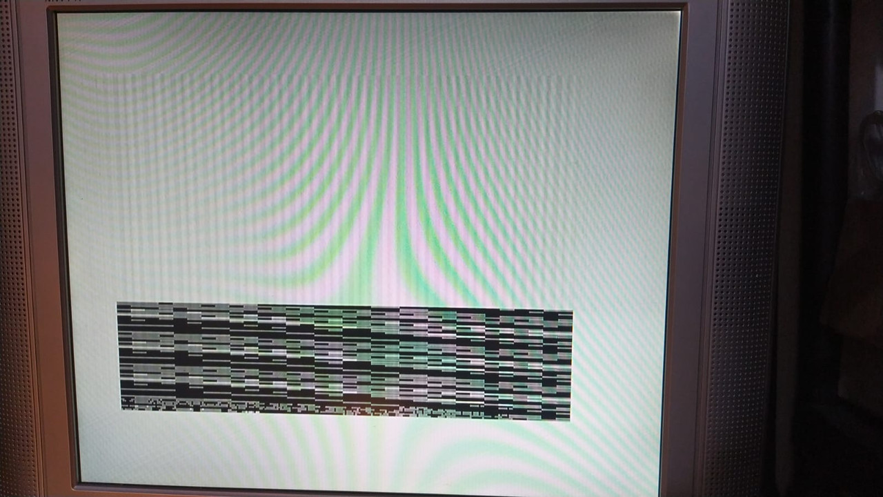
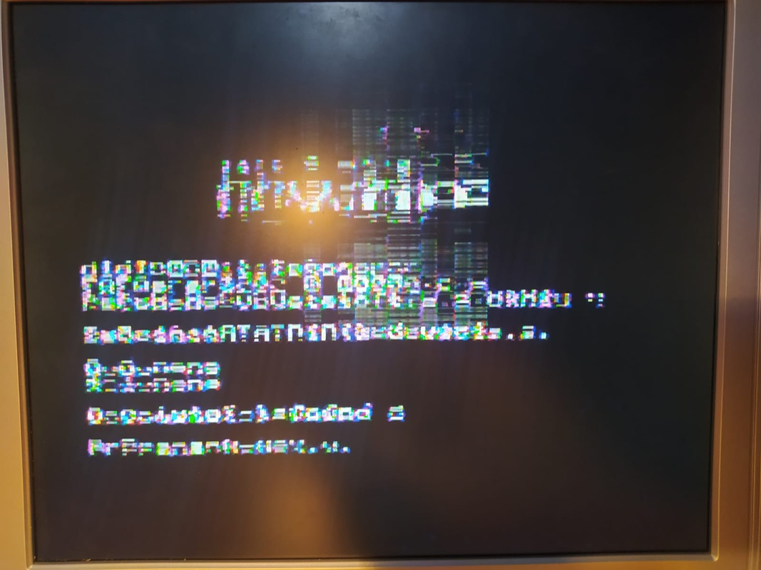
Yes, the LM1889 needs a 12V supply, otherwise it won’t work and you will just get a monochrome display, or a display with messed up colour.

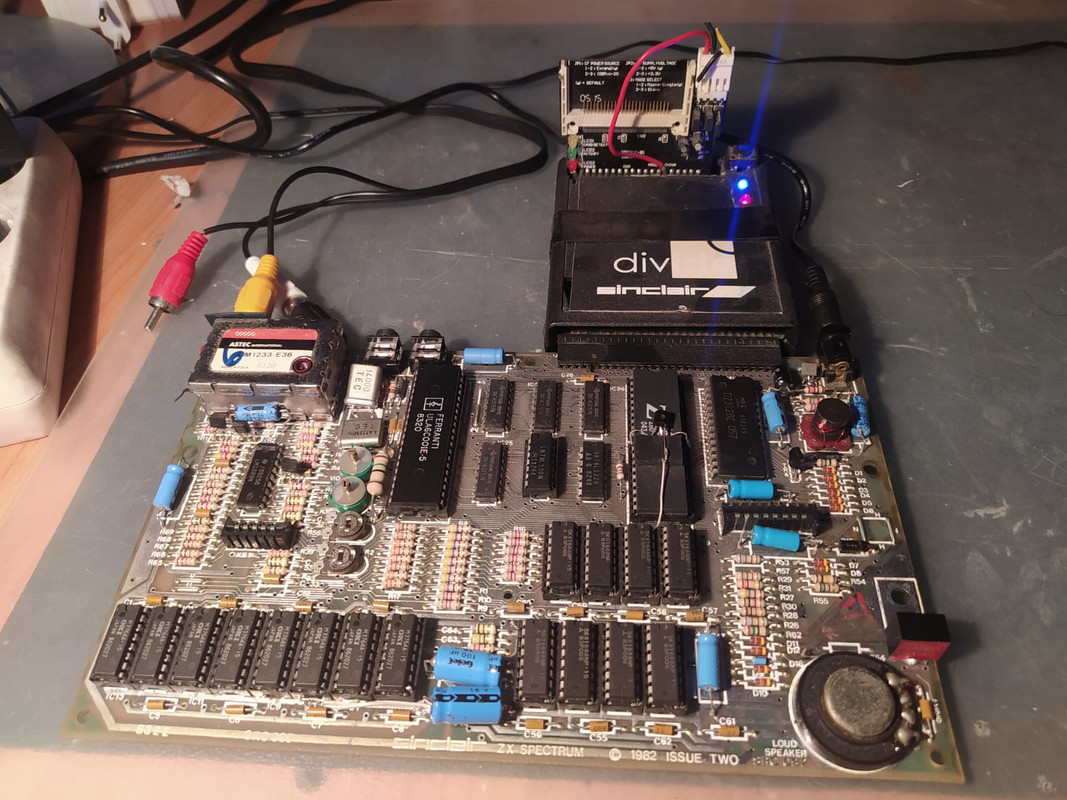
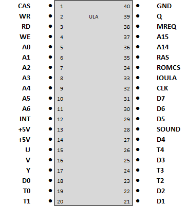
The issue two board should work with any ULA except the 5C102E normally found in issue one boards or early issue two boards, as this ULA needs the ‘dead cockroach’ modification board for it to work properly.

Do you have another ULA to test with?

Mark
:!: Standby alert :!:
“There are four lights!”
Step up to red alert. Sir, are you absolutely sure? It does mean changing the bulb :dance
Looking forward to summer later in the year.
Post Reply