Almost working ZX Spectrum issue 3 - Help?

For experts to discuss very technical stuff and newbies to ask why the Spectrum they bought off ebay doesn't work.
Post Reply
User avatar
Mic
Drutt
Posts: 8
Joined: Sun Mar 20, 2022 7:08 am
Location: The Netherlands

Almost working ZX Spectrum issue 3 - Help?

Post by Mic »

Hi,

New member here.

I have a ZX Spectrum 48K issue 3. Which was in a bad condition when I got it.
With the help of internet and this forum I got to a point that it's almost working correctly, but I still have some problems.
This is my first ZX Spectrum, but have done all sorts of repairs on other retro consoles.

Problems it had in the beginning:
  • Did not show anything on the screen most of the time, and if it did it was garbage.
  • Voltages were way off.

Things I've done to fix it:
  • Recapped the board
  • Replaced TR4 en TR5
  • Replave voltage regulator.
  • Composite mod
  • Socketed all lower RAM (but not replaced with other chips)
  • Replaced keyboard membrane
All voltages are OK now.
And this got me to a point that its booting (most of the time) and I can type stuff.

Problems I still have:
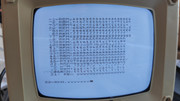
  • Part of screen unreadable. Several columns and several rows are not displayed correctly and are flashing. See picture (flashing not visible in still image, but all the 'bad' characters are flashing).
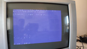
  • Soms weird ghosting (not composite ghosting, but rather a copy/shadow of characters on a seperate line). See picture.
  • Not always booting correctly, when when booted correctly it runs stable and I can do eveything.
  • Not loading programs from tape or from audio from laptop. It starts loading, but quits. Can't read errors.


To rule out some causes:
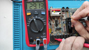
  • I tried different power supplies, all with the same result. For testing I mostly use my bench power supply.
  • I undid the composite mod to rule out that as a problem. With I had the same results with RF. So I did the composite mod again.
This is the only Spectrum I have, so no spare parts laying around.
I don't have an oscilloscope (still want one) to measure the finer details of the signal.
Having troubles loading programs makes it hard to run diagnostics. Having hard to read video, makes it hard to use simple diagnostic basic programs.

My questions:
What can cause said problems?
What is the best thing to test or try next?

Any suggestions would be appreciated.

Image

Image

Image
User avatar
Tiger
Dizzy
Posts: 76
Joined: Thu Oct 28, 2021 5:42 am
Location: Germany

Re: Almost working ZX Spectrum issue 3 - Help?

Post by Tiger »

IMHO it seems a Lower-RAM fault. Because you build in sockets - is there a change if you swap the 4116's from one socket to the other? If so, you'll find the faulty IC also possible is a broken/shortened Data-line (if swapping doesn't make any difference) on the pcb. IC3 and/or IC4 (74LS157) are also possible as one of the resistors in the adress lines (R17-R23 - 330 ohms) ... Worst case: the ULA :shock:
User avatar
Mic
Drutt
Posts: 8
Joined: Sun Mar 20, 2022 7:08 am
Location: The Netherlands

Re: Almost working ZX Spectrum issue 3 - Help?

Post by Mic »

Thanks for the quick response.
Good idea swapping the 4116's. I'll try that first in different configurations. And will come back to share the results.

I sure hope it's not the ULA though.
User avatar
Mic
Drutt
Posts: 8
Joined: Sun Mar 20, 2022 7:08 am
Location: The Netherlands

Re: Almost working ZX Spectrum issue 3 - Help?

Post by Mic »

Well, swapping the 4116's did't do anything. In any configuration I still have the same problems on screen. The same unreadable characters in the same rows and columns.

What can I do to test the other possible cause you mentioned? With the IC3 and/or IC4?
User avatar
Tiger
Dizzy
Posts: 76
Joined: Thu Oct 28, 2021 5:42 am
Location: Germany

Re: Almost working ZX Spectrum issue 3 - Help?

Post by Tiger »

First check for +3V at IC1 pin 13 - if not - change C30.
If that is not the case, check if there is a bad connection in the data or address lines. You could test it by removing the 4116's and take a multimeter.
All pin's must be connected within like the example of the yellow lines in the picture (ipn1 with every pin 1, pin 3 with every pin 3, pin 4...)
Image
Only the green lines are connected from pin 2 to pin 14 for each 4116 by itself. This pin2/pin14 connection is a separate data-line. IC6 is D0 wich must be connected to pin 18 ULA, IC7 is D1 -> pin 21 ULA, IC8 is D2 pin 22 ULA, IC9 is D3 pin 25 ULA, IC10 is D4 pin 27 ULA, IC11 is D5 pin 29 ULA, IC12 is D6 pin 30 ULA, IC13 is D7 pin 31 ULA. I think there is no shortcut between the IC-pin's, your screenshot looks more that there is a signal lost, so I think that one of the data-lines to the ULA is broken.
Also it is possible that this screen is a result of problems in the adress-lines (ULA pin 5-11 = A0-A6) wich are connected to the 4116's (pin5=A0, pin7=A1, pin6=A2, pin12=A3, pin11=A4, pin10=A5, pin13=A6). There must also a connection from 4116' pin 4 to ULA pin35, 4116's pin15 to ULA pin1 and 4116's pin3 to ULA pin4. If all of this is given and there is no shortcut between the adress-lines (e.g. 0 ohms between A0 and A2), then check R17-R23 and R32 (330ohm). Testing IC3 or IC4 in circuit isn't possible I think (there is no "piggy-pack-solution"), so you have to replace them - and if all that don't help it is the ULA. But the best test is not to take a good ULA from an good board to your board (if one of the other components is faulty you could destroy the new one) better is to place your ULA into a board which was working. If there is the same fault after swapping the ULA at the other board you could be sure that the ULA is the problem ...
User avatar
Mic
Drutt
Posts: 8
Joined: Sun Mar 20, 2022 7:08 am
Location: The Netherlands

Re: Almost working ZX Spectrum issue 3 - Help?

Post by Mic »

Thanks for the details instructions.
Here are my (strange) results:

(edit: colors and photo's addes)

ULA Pin 13 reads 3.3 V (guess that's within the limits)
Replaced the capacitor anyway. The old one measured 70 nF (out of circuit) which is not 47 nF that it should be. Still 3.3V though, which is tolerated I think. -> OK

Resistors R17 - R23: 330 ohm -> OK
R32 = 100 ohm. But I think thats ok according to manual. -> OK (although you said 330 ohm)


Testing address lines from ULA to 4116:

Not OK?
I have connections, but to different pins. Which is very strange?
I have the following connections from ULA pins to 4116 pins:
ULA A0 pin 5 -> 4116 pin 7 -> NOT OK
ULA A1 pin 6 -> 4116 pin 11 -> NOT OK
ULA A2 pin 7 -> 4116 pin 5 -> NOT OK
ULA A3 pin 8 -> 4116 pin 13-> NOT OK
ULA A4 pin 9 -> 4116 pin 12-> NOT OK

ULA A5 pin 10 -> 4116 pin 10 -> OK
ULA A6 pin 11 -> 4116 pin 6 -> NOT OK

What am I doing wrong? How can I have different connections and still see stuff on screen?
See added pictures from me measurements of ULA A0. Which doest not connect to pin 5 but to pint 7 on he 4116.

4116' pin 4 to ULA pin35 -> OK
4116's pin15 to ULA pin1 -> OK
4116's pin3 to ULA pin4 -> OK
no shortcut between the adress-lines (e.g. 0 ohms between A0 and A2) -> OK


So the main question now is:
How can I have different connections from the 4116's to ULA in the address lines? Or am I doing something stupid and measuring it wrong?

Image
Image
User avatar
Tiger
Dizzy
Posts: 76
Joined: Thu Oct 28, 2021 5:42 am
Location: Germany

Re: Almost working ZX Spectrum issue 3 - Help?

Post by Tiger »

:shock: R32 is right with 100 Ohms (it is the value of the part-list, the schematic is wrong)
The ULA - 4116 address-line connections are from an issue 2 schematic which was very good readable, but it seems there are differences between the issues, so in an issue 3 schematic it is totally different
ULA pin5 -> 4116 pin7
ULA pin6 -> 4116 pin11
ULA pin7 -> 4116 pin5
ULA pin8 -> 4116 pin13
ULA pin9 -> 4116 pin12
ULA pin10-> 4116 pin10
ULA pin11-> 4116 pin6
So your address-line measurements are ok
that confused me - because in the 4116 datasheet there is
A0 = pin 5 - A1 = pin 7 - A2= pin 6 - A3= pin 12 - A4= pin 11 - A5= pin 10 - A6= pin 13.
The book "The Spectrum ULA" says the pins for ULA are as follows:
A0 = pin 5 - A1 = pin 6 - A2= pin 7 - A3= pin 8 - A4= pin 9 - A5= pin 10 - A6= pin 11.
It seems there are differences between the ULA-types which vary in the pcb issues and there is a mismatch in the addressbus numbers.
User avatar
Mic
Drutt
Posts: 8
Joined: Sun Mar 20, 2022 7:08 am
Location: The Netherlands

Re: Almost working ZX Spectrum issue 3 - Help?

Post by Mic »

Ah thanks, that means all is allright.
It confused me a lot, because all the pinouts I could find were as you described.

That leaves me with these things I can try:
  • Swap out lower RAM for known working ones
  • Test my ULA in a known working machine
At the moment I don't have a working spectrum and don't know anyone with one. But of course I can order some working RAM chips to try option 1.

Any other ideas?
Should I try recapping the ceramic capacitors for example?
User avatar
Tiger
Dizzy
Posts: 76
Joined: Thu Oct 28, 2021 5:42 am
Location: Germany

Re: Almost working ZX Spectrum issue 3 - Help?

Post by Tiger »

Because you swapped the lower RAMs within, with no different picture, they are probably ok. IC 3 und IC 4 are not very expensive, so I would change them - but more and more I think it's the ULA ...
User avatar
Mic
Drutt
Posts: 8
Joined: Sun Mar 20, 2022 7:08 am
Location: The Netherlands

Re: Almost working ZX Spectrum issue 3 - Help?

Post by Mic »

Oh no, my poor ULA. I hope she's ok.

I'll try the IC3 & IC4 replacements first.
Have to order them and will share my results. Will take a few days.

Worst case, my ULA is gone, but I still had fun repairing and analysing, and I learned a lot.
Thank you for all the help and instructions for now! Really appreciate it!

To be continued.
User avatar
Tiger
Dizzy
Posts: 76
Joined: Thu Oct 28, 2021 5:42 am
Location: Germany

Re: Almost working ZX Spectrum issue 3 - Help?

Post by Tiger »

👍
kegnkiwi
Dizzy
Posts: 94
Joined: Fri Dec 31, 2021 6:48 pm

Re: Almost working ZX Spectrum issue 3 - Help?

Post by kegnkiwi »

You have what looks like a very similar problem to me but mine is worse as nothing is responding. I have replaced the lower ram with a new ram board, replaced ic2/3 and recapped the board, and changed the transistors. I have as a last resort ordered a used ula that are selling on ebay at the moment. UK cost £20.00 pus £3.50 shipping. When it arrives I will let you know.
User avatar
Mic
Drutt
Posts: 8
Joined: Sun Mar 20, 2022 7:08 am
Location: The Netherlands

Re: Almost working ZX Spectrum issue 3 - Help?

Post by Mic »

If it really is a similar problem, I would love to know whether the ULA replacement fixed it or not.

In the mean time I socketed IC3 & IC4. Swapped them, with no difference.

Now started on replacing all ceramic capacitors. Which all measured way higher values than expected. (or is that normal? 70 - 80 nF for a 47 nF capacitor?)

And then I ran out of 47nF capacitors. Boy, this thing needs a lot. Had to order new ones.
Not seen a great difference yet, but I have the feeling the image quality improved. But maybe I just want to believe that...

Will take a while for my new parts coming in, but I'll keep you posted on my progress.
User avatar
Tiger
Dizzy
Posts: 76
Joined: Thu Oct 28, 2021 5:42 am
Location: Germany

Re: Almost working ZX Spectrum issue 3 - Help?

Post by Tiger »

New ceramic caps are a good idea. Think about C5 to C8 and take 220nF types instead of 47nF, to eliminate the "jailbar effect". Some mystery screen-failures I had on ZX Spectrum's resulted in broken ceramic capacitors. The axial types tend to break at the wire connections ...
User avatar
Mic
Drutt
Posts: 8
Joined: Sun Mar 20, 2022 7:08 am
Location: The Netherlands

Re: Almost working ZX Spectrum issue 3 - Help?

Post by Mic »

Update two years later: It is fixed!

I replaced all caps, but that did'nt fix my problem.

But finally I got my hands on another zx spectrum. That one does not work. Probably RAM issue.

I tried the ULA from that unit in my zx spectrum, and now I have a clear image! Hurray!
So it was the ULA all this time.
So if anyone has the same problem as I had, it probably is the ULA.
Post Reply