Pico based Spectrum ROM interface (photoessay)

For experts to discuss very technical stuff and newbies to ask why the Spectrum they bought off ebay doesn't work.
dfzx
Manic Miner
Posts: 683
Joined: Mon Nov 13, 2017 6:55 pm
Location: New Forest, UK
Contact:

Pico based Spectrum ROM interface (photoessay)

Post by dfzx »

A Spectrum external ROM interface is a fairly straightforward device to create. The Spectrum is designed to support them, and we've had them since the 80s. Relatively simple they may be, but no fledgling ZX-hardware-hacker can claim their stripes before they've made one. So I figured I'd better make one. :)

The normal way to make one of these is to use a standard ROM or EEPROM chip, but where's the fun in retreading so much ground? I did mine a different way. I used a Raspberry Pi Pico microcontroller which I programmed to emulate a ROM device.

The basic design involves setting 16 of the Pico's General Purpose Input/Output lines (GPIOs) as inputs, then connecting them to the 16 lines of the Z80's address bus, along with the Z80's /MREQ ("memory request") line. When /MREQ goes active and the address on the address bus is in the range $0000 to $3FFF, that means the Z80 is accessing a byte in the ROM. When this happens the Pico needs to go to the 16K memory image it's using as the ROM, find the byte at the offset the Z80 is requesting, and apply the 8 bits of that byte to 8 output GPIOs connected to the Z80's data bus. Thus when the Z80 does a ROM memory request the byte appears on its data bus and the Z80 has no idea it just spoke to a microcontroller instead of a 1980s ROM chip.

The Raspberry Pi Pico does have a bit of a drawback for this sort of project though: it's only got 26 GPIO pins. With 16 needed for the address bus and 8 more needed for the data lines, plus /MREQ, that's pretty much them all used before anything else is considered. No one said this was going to be easy. :)

The real issue is speed. The RP2040 processor on the Pico is clocked at 133MHz. Page 8 of the Z80 manual says that the timing for the Z80's "M1", the instruction-fetch cycle, is the most time critical. In this case the Z80 puts the address it wants to read on the address bus then activates /MREQ. The Z80 then reads the data byte off the data bus exactly one and a half clock cycles after /MREQ goes active. There's no "it's ready" flag or anything like that. The Z80 just assumes the memory makes the data byte available quickly enough. On the Spectrum's 3.5MHz Z80, one and a half clocks is (taps on calculator) 4.28571428571e-07 seconds, which is about 430 nanoseconds, a nanosecond being one billionth of a second. Most machine code instructions on the RP2040 processor execute in one clock cycle (unlike the Z80 which takes anywhere between between 4 and 23 cycles per instruction). One clock cycle at 133MHz is about 7.5ns, so in 430ns the Pico can run (tap-tappity-tap) 57 machine code instructions. Hmmm. 57 machine code instructions to read the GPIOs, sort out the address lines into a 16 bit number, find the value at that offset in a 16K buffer containing a ROM image, then sort out the 8 bits of that value and put them on 8 GPIOs ready for the Z80 to pick up? Might be a bit tight, this.

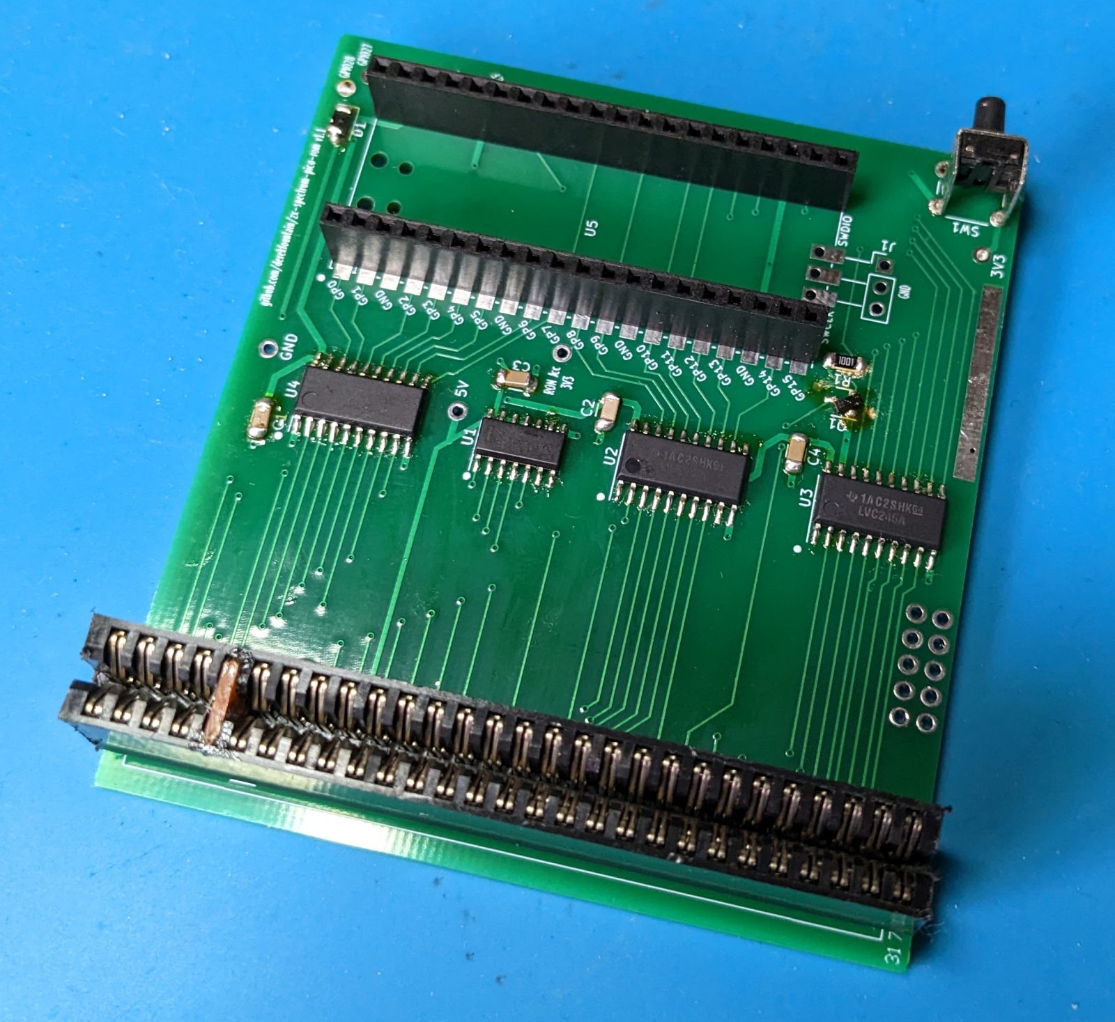
"Oh well," I thought. "Only one way to find out, and it's not going to build itself." So I made a design, sent it off for fabrication, and when the boards arrived I built one. I don't tend to plug v1.0 experimental boards straight into a Spectrum, so, with not even a Pico attached, I powered it directly:
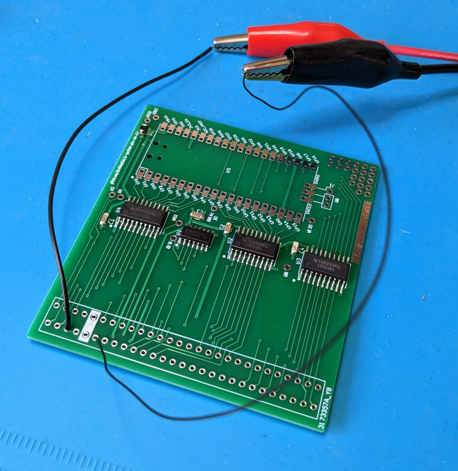
Image

Nothing went bang and the bench PSU said nominal current draw, so I added the edge connector and the Pico:
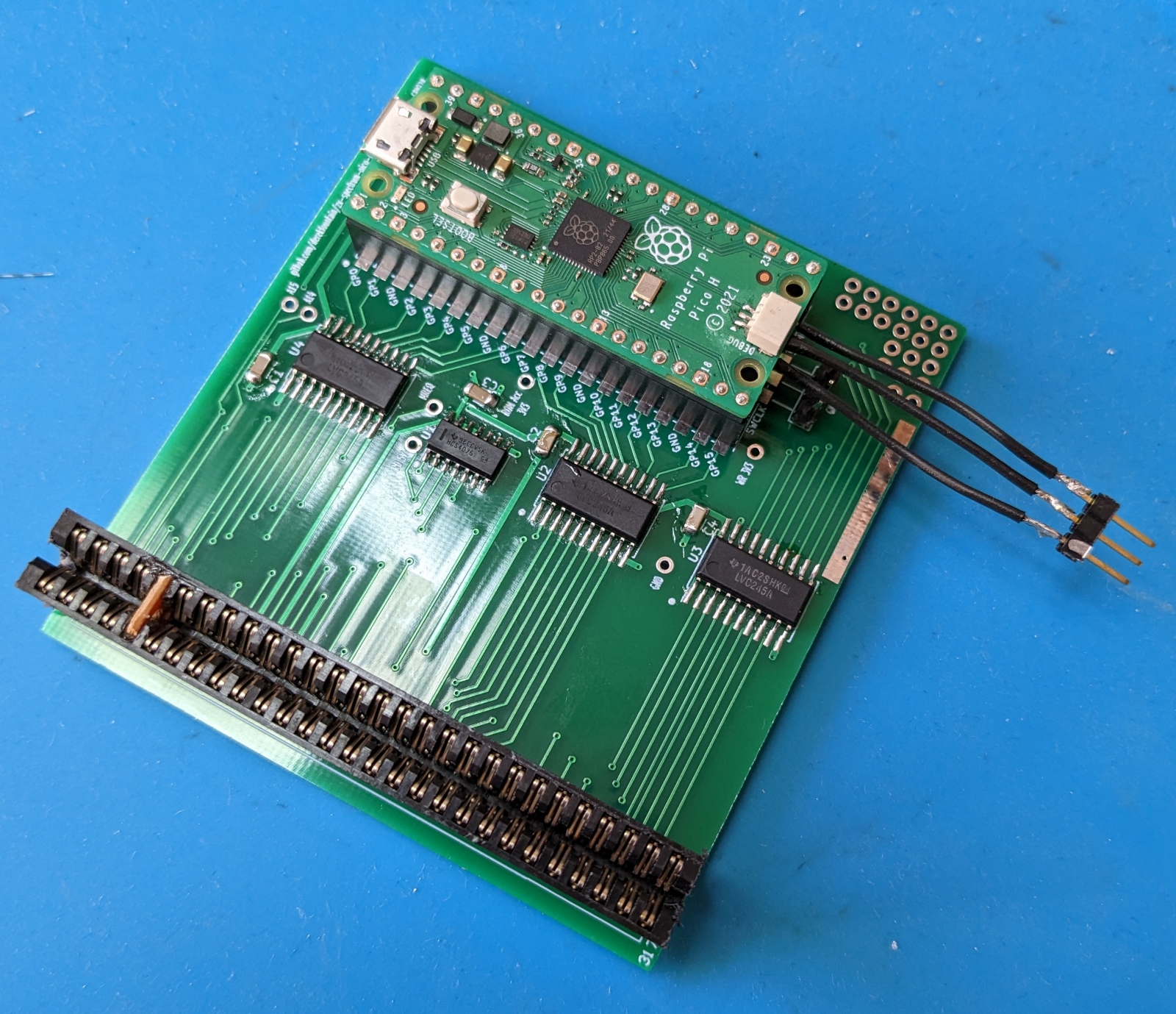
Image

I wrote the initial software for the Pico, programmed it, and plugged the device in. Did it work? It did not.
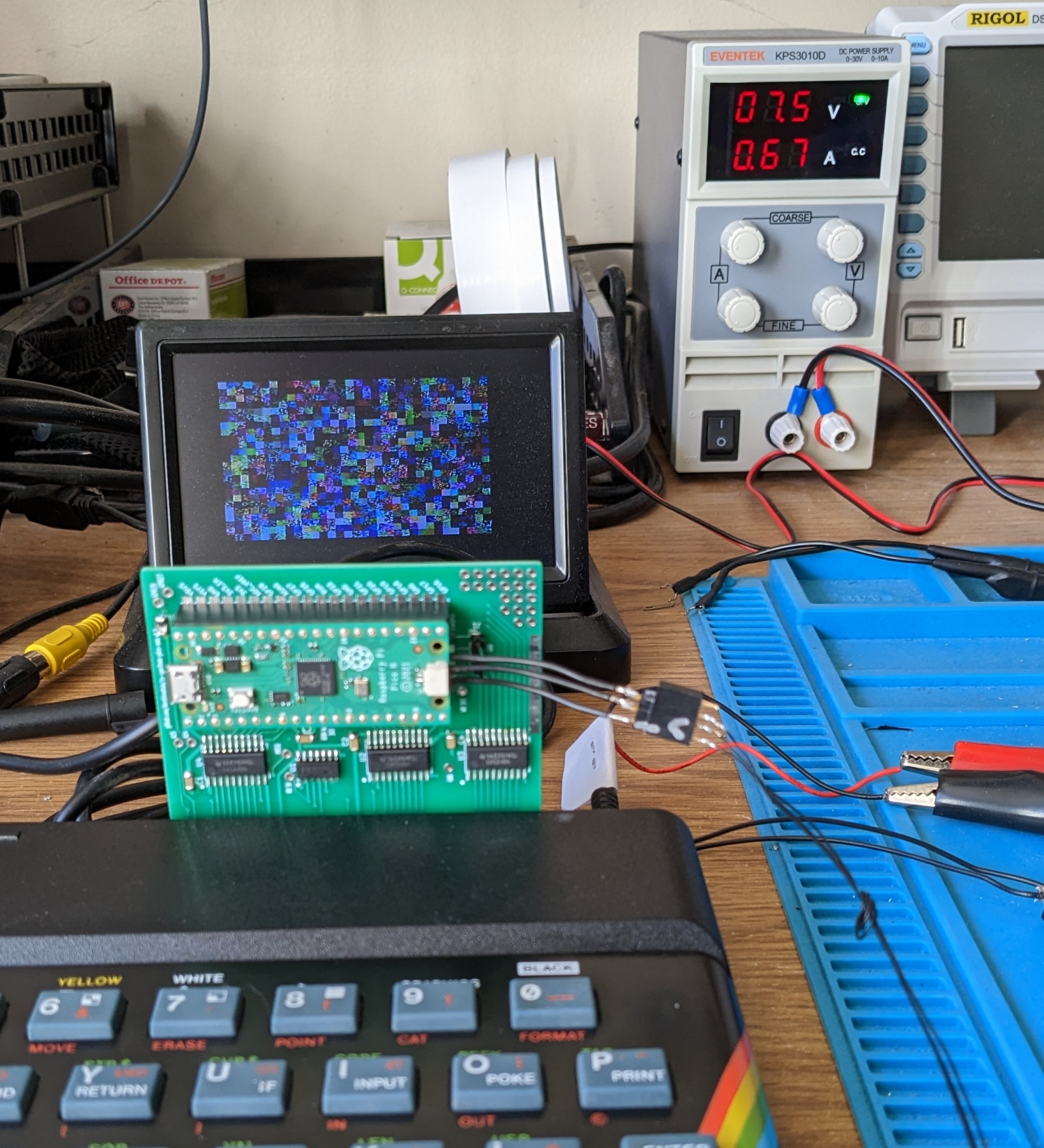
Image

It turned out that the initial problems were all Pico software related, and after some debugging and updating, I got it working. The hardware prototype was actually correct first time. Note how I changed the copyright date in the ROM image so I could tell my ROM was working and I wasn't just seeing the Spectrum's ROM:
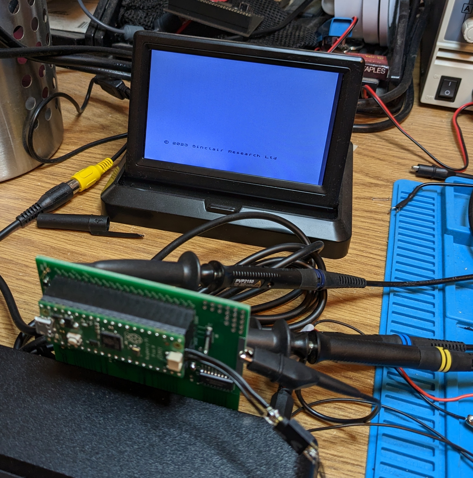
Image

The board is designed to take complete and permanent control of the ROM image. (For the initiated, it permanently asserts the /ROMCS line, disabling the Spectrum's ROM chip.) The default 16K ROM image in the Pico's memory is the original 1982 ROM, so with the emulation software working the Pico supplies the exact bytes the original ROM chip does. But it can actually supply whatever it likes.

The idea at this point was to have several ROM images on board and have the active one selectable. So the plan was to load up some ROMs - original, bugfixed, diagnostics, GOSH, the games ones - and have a selection method the user could use to select the one they want. The Pico code for fetching a byte from the active ROM image and handing it back to the Z80 is this:

Code: Select all

    uint8_t rom_value = *(rom_image_ptr+rom_address);
    gpio_put_masked( DBUS_MASK, rom_value );

The rom_address is the address the Z80 has asked for. rom_image_ptr is a pointer to the 16K buffer holding the currently active ROM image. Therefore changing the ROM which the Spectrum sees is as simple as changing the data buffer rom_image_ptr points to. I could do this on a button press, or programmatically.

The important thing the prototype was missing was the ability of the Pico to reset the Z80. The Pico would switch the ROM and the Z80 would continue running as its program was abruptly changed underneath it. This didn't end well. So I needed to add the ability for the Pico to change the ROM image, then reset the Z80. I'd had some vague idea about using the /WR line to detect writes to ROM. In practise this seemed superflous, so I cut those tracks and wired up the Z80's /RESET line via a transistor so the Pico could pull the /RESET low. I added a couple of switches, which led to this:
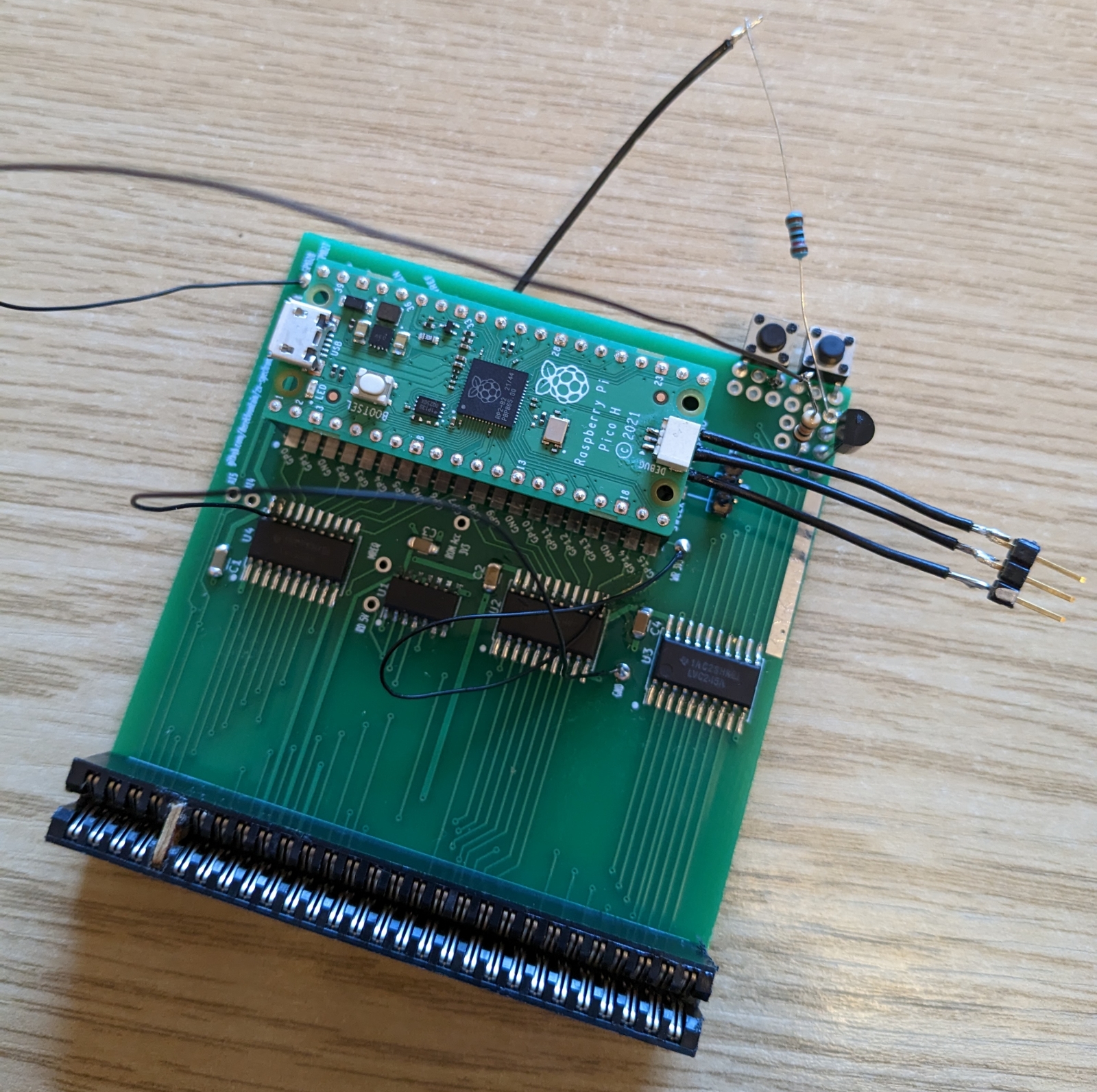
Image

This worked reasonably well. The switches were a bit wobbly, and it turned out I only needed one, but the Pico being able to control the Z80's reset solved a lot of problems. So I sent the v1.1 design off for fabrication. They arrived back:
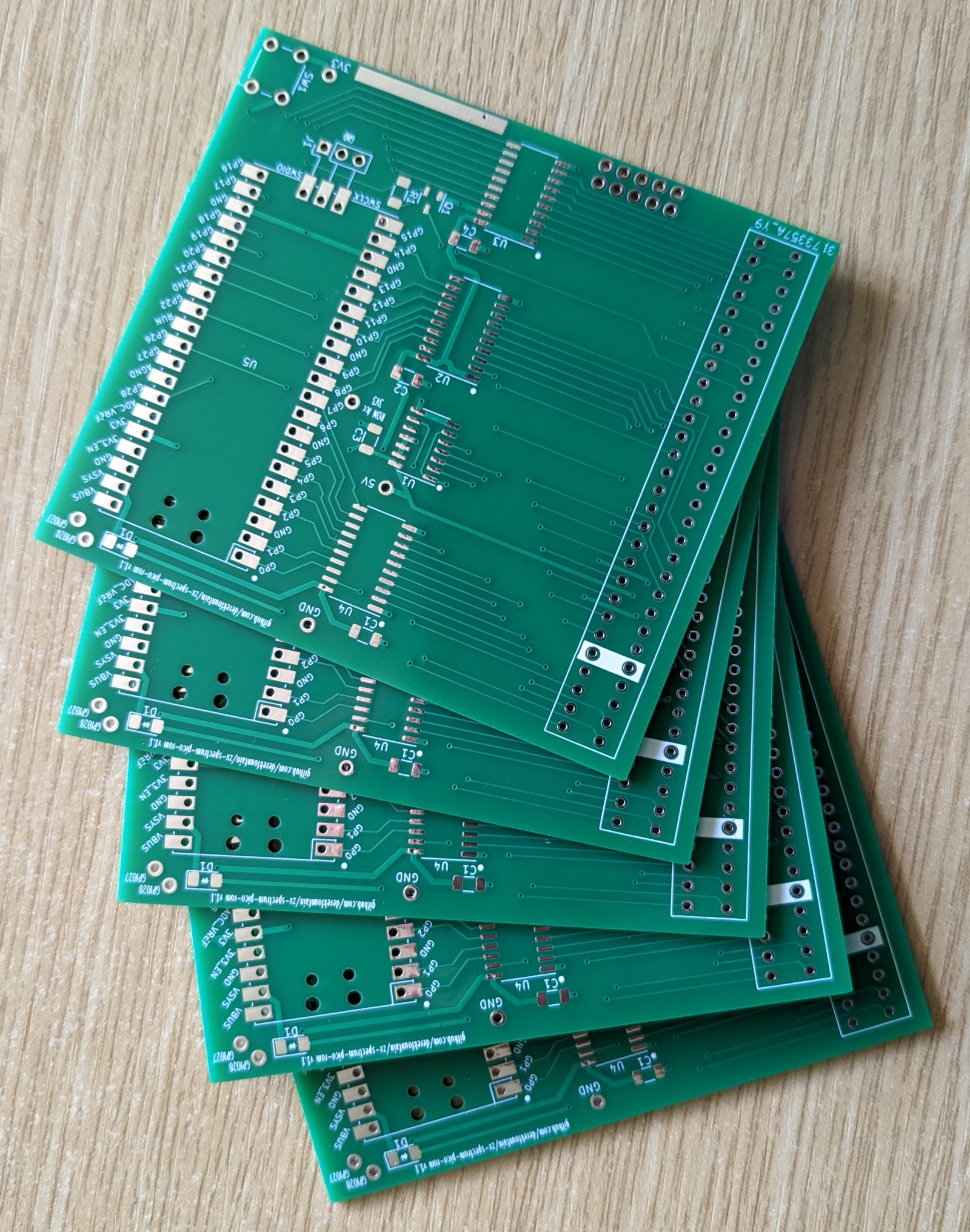
Image

and I built one:

Image

This board needed a couple of fixes (notice the rotated transistor to the bottom right of the Pico sockets, oops). But it works. The software in the Pico cycles the list of compiled-in ROMs when the button is pressed. Here's a wobbly demonstration YT video:


The project is open and free under the GPL, its design and source files are all available on my Github page.
Derek Fountain, author of the ZX Spectrum C Programmer's Getting Started Guide and various open source games, hardware and other projects, including an IF1 and ZX Microdrive emulator.
User avatar
lister_of_smeg
Microbot
Posts: 145
Joined: Thu Nov 16, 2017 1:44 pm

Re: Pico based Spectrum ROM interface (photoessay)

Post by lister_of_smeg »

Nice work! You can save GPIO by ORing bits 15 and 14 of the address bus, /MREQ and /RD. (if you're not already doing so!)
User avatar
Joefish
Rick Dangerous
Posts: 2059
Joined: Tue Nov 14, 2017 10:26 am

Re: Pico based Spectrum ROM interface (photoessay)

Post by Joefish »

Nice board - where did you get the fabrication done, and was it cheap?
dfzx
Manic Miner
Posts: 683
Joined: Mon Nov 13, 2017 6:55 pm
Location: New Forest, UK
Contact:

Re: Pico based Spectrum ROM interface (photoessay)

Post by dfzx »

lister_of_smeg wrote: Fri Feb 17, 2023 5:58 pm Nice work! You can save GPIO by ORing bits 15 and 14 of the address bus, /MREQ and /RD. (if you're not already doing so!)
Heh, yes, I decided against writing out a fully detailed description of how it works. :)

The smaller IC you see on the board is a 3-way OR gate which ORs A14, A15 and /MREQ. If all are 0 (i.e. the result of the OR is a 0) then the Z80 is doing a memory access of the ROM. The result goes into a Pico GPIO, and it's that GPIO which tells the Pico it needs to take action. The OR gate saves 2 GPIOs.

I skipped the /RD line (I was out of GPIOs) so ROM reads and writes are treated the same (which is what the Interface 2 does, actually).
Derek Fountain, author of the ZX Spectrum C Programmer's Getting Started Guide and various open source games, hardware and other projects, including an IF1 and ZX Microdrive emulator.
dfzx
Manic Miner
Posts: 683
Joined: Mon Nov 13, 2017 6:55 pm
Location: New Forest, UK
Contact:

Re: Pico based Spectrum ROM interface (photoessay)

Post by dfzx »

Joefish wrote: Fri Feb 17, 2023 6:25 pm Nice board - where did you get the fabrication done, and was it cheap?
Everyone's favourite, JLCPCB.

It's a simple 2 layer board, so 5 pieces cost £1.61. That is not a misprint. Of course, by the time you've paid postage and duties the final cost is well in excess of £7. :lol:
Derek Fountain, author of the ZX Spectrum C Programmer's Getting Started Guide and various open source games, hardware and other projects, including an IF1 and ZX Microdrive emulator.
User avatar
Seven.FFF
Manic Miner
Posts: 744
Joined: Sat Nov 25, 2017 10:50 pm
Location: USA

Re: Pico based Spectrum ROM interface (photoessay)

Post by Seven.FFF »

For it to be widely useful, consider adding logic for the 32KB ROM in 128/+2, and the 64KB ROM and all-RAM mode in +2A/+3. And the correct overrides for any IF1/IF2/divMMC/Multiface/Spectranet/etc plugged in after it.

I have one of ZXGuesser’s designs that handles that nicely for a +2A/+3, allowing you to switch to the +3e ROMs with the divMMC used to store the +3e hard drives.
Robin Verhagen-Guest
SevenFFF / Threetwosevensixseven / colonel32
NXtel NXTP ESP Update ESP Reset CSpect Plugins
User avatar
TomD
Manic Miner
Posts: 379
Joined: Tue Nov 13, 2018 9:47 am
Location: Leeds UK
Contact:

Re: Pico based Spectrum ROM interface (photoessay)

Post by TomD »

Excellent work. Will have a good read of the GitHub as very interested in how you got it all working.

TonD
Retro enthusiast and author of Flynn's Adventure in Bombland, The Order of Mazes & Maze Death Rally-X. Check them out at http://tomdalby.com
User avatar
TomD
Manic Miner
Posts: 379
Joined: Tue Nov 13, 2018 9:47 am
Location: Leeds UK
Contact:

Re: Pico based Spectrum ROM interface (photoessay)

Post by TomD »

Noticed the use of level shifters for the 3v3 to 5v and am wondering if you’ve tried without. I had something similar with my Pico Microdrive emulator and ended up with a simpler diode setup as the Interface 1 was more than happy with a 3v input. For the reverse I used a diode to protect the Pico from the 5v and then pulled the gpio high.

The Spectrum may not be as forgiving though but I might order one and give it a try.

TomD
Retro enthusiast and author of Flynn's Adventure in Bombland, The Order of Mazes & Maze Death Rally-X. Check them out at http://tomdalby.com
dfzx
Manic Miner
Posts: 683
Joined: Mon Nov 13, 2017 6:55 pm
Location: New Forest, UK
Contact:

Re: Pico based Spectrum ROM interface (photoessay)

Post by dfzx »

TomD wrote: Sat Feb 18, 2023 12:21 pm Noticed the use of level shifters for the 3v3 to 5v and am wondering if you’ve tried without. I had something similar with my Pico Microdrive emulator and ended up with a simpler diode setup as the Interface 1 was more than happy with a 3v input. For the reverse I used a diode to protect the Pico from the 5v and then pulled the gpio high.
For the Pico->Spectrum direction the level shifters don't actually do anything. The shifters are powered at 3V3, so that's the maximum voltage they put out. Thus the 3V3 from the Pico goes through the level shifter and arrives at the Spectrum at 3V3, which, it turns out, is enough for the Spectrum to register as a logic 1 on a bus line.

For the Spectrum->Pico direction the level shifters are necessary because the Pico is 3V3 and using the Spectrum's 5V as a direct input will fry the GPIO. Or at least that's the common wisdom. This comment from Eben Upton (Raspberry Pi head chap) on Hackaday confirms the Pico GPIOs are in fact 5V tolerant, so the level shifters probably aren't required. I've accidentally connected a Spectrum line to a Pico and nothing bad happened. I've got a friend who has been experimenting with providing a Pico with 5V and after many hours of runtime everything seems OK for him.

The danger would be that the source machine (the Spectrum in this case) produces more than 5V for one of these signals. I don't think it ever does that. As far as I've ever seen, the internal voltages for the Spectrum are always around the 4.75V mark. Someone with more experience might be able to confirm what the maximum voltage on those buses might be?

Anyway, at the moment it looks like the level shifters probably aren't required, which would be excellent for this sort of project.
Derek Fountain, author of the ZX Spectrum C Programmer's Getting Started Guide and various open source games, hardware and other projects, including an IF1 and ZX Microdrive emulator.
User avatar
TomD
Manic Miner
Posts: 379
Joined: Tue Nov 13, 2018 9:47 am
Location: Leeds UK
Contact:

Re: Pico based Spectrum ROM interface (photoessay)

Post by TomD »

dfzx wrote: Sun Feb 19, 2023 10:39 am For the Pico->Spectrum direction the level shifters don't actually do anything. The shifters are powered at 3V3, so that's the maximum voltage they put out. Thus the 3V3 from the Pico goes through the level shifter and arrives at the Spectrum at 3V3, which, it turns out, is enough for the Spectrum to register as a logic 1 on a bus line.

For the Spectrum->Pico direction the level shifters are necessary because the Pico is 3V3 and using the Spectrum's 5V as a direct input will fry the GPIO. Or at least that's the common wisdom. This comment from Eben Upton (Raspberry Pi head chap) on Hackaday confirms the Pico GPIOs are in fact 5V tolerant, so the level shifters probably aren't required. I've accidentally connected a Spectrum line to a Pico and nothing bad happened. I've got a friend who has been experimenting with providing a Pico with 5V and after many hours of runtime everything seems OK for him.

The danger would be that the source machine (the Spectrum in this case) produces more than 5V for one of these signals. I don't think it ever does that. As far as I've ever seen, the internal voltages for the Spectrum are always around the 4.75V mark. Someone with more experience might be able to confirm what the maximum voltage on those buses might be?

Anyway, at the moment it looks like the level shifters probably aren't required, which would be excellent for this sort of project.
That's good to know. I use a diode set-up to protect the Pico from the 5V input and using Schottky diodes instead of 1N4148s helps with the voltage drop. Simply pulling the GPIO high means it can act as an input fine, as when the output from the Interface 1 (and assume the Spectrum) goes to 0 it pulls the GPIO low.

Time to learn KiCAD so I can take a look at the board :-)

TomD
Retro enthusiast and author of Flynn's Adventure in Bombland, The Order of Mazes & Maze Death Rally-X. Check them out at http://tomdalby.com
User avatar
RMartins
Manic Miner
Posts: 776
Joined: Thu Nov 16, 2017 3:26 pm

Re: Pico based Spectrum ROM interface (photoessay)

Post by RMartins »

Nice project and exercise and it's always fun.
But gives me the vibes of "killing a fly with a hammer".
dfzx
Manic Miner
Posts: 683
Joined: Mon Nov 13, 2017 6:55 pm
Location: New Forest, UK
Contact:

Re: Pico based Spectrum ROM interface (photoessay)

Post by dfzx »

RMartins wrote: Sun Feb 19, 2023 8:36 pm But gives me the vibes of "killing a fly with a hammer".
Goodness, no, not at all. Using a microcontroller to emulate an old piece of technology has become a useful technique in recent years. As original devices have got more scarce and unreliable with age, and microcontrollers like the RP2040 have got faster and faster, what used to be the realm of FPGAs and CPLDs has now become open to 'C' programmers on relatively simple, commodity devices.

The ability to run significant and useful programs between clock cycles of a 1980s CPU opens up a world of reproduction and invention. Here's a project using one to recreate Datapaks on the Psion Organiser. Emulating old PC cards is also quite common.

Connecting a Pico directly to a Spectrum's Z80 in order to emulate a piece of vintage hardware at MHz speeds is something I've not seen done before. As far as I'm aware I'm the first person to have done it.
Derek Fountain, author of the ZX Spectrum C Programmer's Getting Started Guide and various open source games, hardware and other projects, including an IF1 and ZX Microdrive emulator.
Gooeyblob
Drutt
Posts: 32
Joined: Sun Nov 08, 2020 4:11 pm

Re: Pico based Spectrum ROM interface (photoessay)

Post by Gooeyblob »

Nice work dfzx!
I've seen this done on the c64 and was planning on doing something similar myself!
You could let the PIO and DMA handle all the gpio/address decoding/data writing and leave the CPU free for other interesting ideas!
dfzx
Manic Miner
Posts: 683
Joined: Mon Nov 13, 2017 6:55 pm
Location: New Forest, UK
Contact:

Re: Pico based Spectrum ROM interface (photoessay)

Post by dfzx »

Gooeyblob wrote: Mon Feb 20, 2023 11:29 am You could let the PIO and DMA handle all the gpio/address decoding/data writing and leave the CPU free for other interesting ideas!
Yes, the RP2040's PIOs are something I've not yet explored, but someone else suggested exactly what you say: PIO and DMA can probably do this all by themselves. In fact, what I have now is all running on one core, so I have another 133MHz core sitting free to do other stuff if I need it. :)
Derek Fountain, author of the ZX Spectrum C Programmer's Getting Started Guide and various open source games, hardware and other projects, including an IF1 and ZX Microdrive emulator.
Gooeyblob
Drutt
Posts: 32
Joined: Sun Nov 08, 2020 4:11 pm

Re: Pico based Spectrum ROM interface (photoessay)

Post by Gooeyblob »

If you used the PIO then it would it would negate the need to overclock the Pico! :)
User avatar
spider
Dynamite Dan
Posts: 1099
Joined: Wed May 01, 2019 10:59 am
Location: Derby, UK
Contact:

Re: Pico based Spectrum ROM interface (photoessay)

Post by spider »

Just a quick "this is impressive" comment.
dfzx
Manic Miner
Posts: 683
Joined: Mon Nov 13, 2017 6:55 pm
Location: New Forest, UK
Contact:

Re: Pico based Spectrum ROM interface (photoessay)

Post by dfzx »

Gooeyblob wrote: Mon Feb 20, 2023 11:59 am If you used the PIO then it would it would negate the need to overclock the Pico! :)
Yes, I've heard nothing but good things about the RP2040's PIOs. Massive performance in simple, programmable hardware. Needs investigation!
Derek Fountain, author of the ZX Spectrum C Programmer's Getting Started Guide and various open source games, hardware and other projects, including an IF1 and ZX Microdrive emulator.
dfzx
Manic Miner
Posts: 683
Joined: Mon Nov 13, 2017 6:55 pm
Location: New Forest, UK
Contact:

Re: Pico based Spectrum ROM interface (photoessay)

Post by dfzx »

spider wrote: Mon Feb 20, 2023 12:55 pm Just a quick "this is impressive" comment.
Thanks @spider ! :)
Derek Fountain, author of the ZX Spectrum C Programmer's Getting Started Guide and various open source games, hardware and other projects, including an IF1 and ZX Microdrive emulator.
SamC
Microbot
Posts: 168
Joined: Sun Sep 29, 2019 9:07 pm

Re: Pico based Spectrum ROM interface (photoessay)

Post by SamC »

Thumbs up for the interesting device!

Would it be possible to increase usability of this interface by adding other ROM and RAM expansions?
There are several very useful programs for lesser-known systems. Their implementation in this device would be easier than a production of separate HW boards. They are e.g.

dev-tools patched by Velesoft for the MB02 RAM: https://velesoft.speccy.cz/
MZ-Basic for the Spectrum 80k: https://sam.speccy.cz/mzbasic.html
LnxCopy for the Ultimate RAM: https://www.ilnx.cz/lnxcopy/
User avatar
RMartins
Manic Miner
Posts: 776
Joined: Thu Nov 16, 2017 3:26 pm

Re: Pico based Spectrum ROM interface (photoessay)

Post by RMartins »

dfzx wrote: Mon Feb 20, 2023 10:43 am Goodness, no, not at all. Using a microcontroller to emulate an old piece of technology has become a useful technique in recent years. As original devices have got more scarce and unreliable with age, and microcontrollers like the RP2040 have got faster and faster, what used to be the realm of FPGAs and CPLDs has now become open to 'C' programmers on relatively simple, commodity devices.
I think the interesting thing is what you mention last in that sentence, allowing programmers to code to interact with or as hardware.
And obviously the challenge in itself, since due to the task at hand there are some limitations, namely required speed.

But using so much computing power, to mimic what a single ROM or FLASH CHIP does seems overkill.
dfzx wrote: Mon Feb 20, 2023 10:43 am The ability to run significant and useful programs between clock cycles of a 1980s CPU opens up a world of reproduction and invention. Here's a project using one to recreate Datapaks on the Psion Organiser. Emulating old PC cards is also quite common.
You can always explore other things, since programming is still more flexible than hardware, but programmable hardware exists for many years and already covers most if not all use cases.

The real benefit might be to lower the barrier to entry to fiddling with hardware.
dfzx wrote: Mon Feb 20, 2023 10:43 am Connecting a Pico directly to a Spectrum's Z80 in order to emulate a piece of vintage hardware at MHz speeds is something I've not seen done before. As far as I'm aware I'm the first person to have done it.
And Kudos to you.

Note that it was not my intention to critique the work per se, but the usefulness of such an endeavor, besides the fun factor and coolness of actually doing it :ugeek: .

I'm wondering what else can be done that is actually useful, in the sense that can not be done easily through programmable hardware ?
dfzx
Manic Miner
Posts: 683
Joined: Mon Nov 13, 2017 6:55 pm
Location: New Forest, UK
Contact:

Re: Pico based Spectrum ROM interface (photoessay)

Post by dfzx »

All sorts of things are possible with it. The key appears to be deciding how the Spectrum and Pico communicate in order to trigger features. I initially thought, for example, that writing to one of the ROM's unused bytes, e.g.:

Code: Select all

POKE 19,2
could cause the Pico to swap to ROM image #2. I didn't do it that way in the end, but only because I wanted to keep the initial version simple.

ROM and RAM are the same from the Pico's perspective. It's just the Pico's onboard memory. You could set the Pico's 16K memory image to "RAM mode" which allows writing and have 64K RAM on the Spectrum. You could use the Pico's flash as non-volatile RAM. You could implement a "suspend" feature for the Spectrum where you switch the ROM to a temporary Z80 program which dumps the whole Spectrum memory out to the Pico for storage on flash ready for retrieval when you "resume".

Banking can be done programmatically. e.g. at location 16381 you could have "JP $0000". When the Pico software spots that instruction being fetched it could page in a new ROM and the Z80 would just "continue" the program from address 0 as the Z80 makes the jump.

You could offer several ROMs as a package which the Pico switches automatically as requested. For example, you could have editor, assembler, debugger programs, which the Pico switches in and out as required. Or office suite programs. Or a graphics and music creativity suite. Or the whole lot actually, the Pico has plenty of space. As long as the Spectrum has a way to tell the Pico what it wants, this becomes possible.

What about a sprite engine? I could compile SP1 into a ROM image and a BASIC program could trigger the Pico to automatically page it in. BASIC can be extended with this device, so new commands can be implemented in a ROM and paged by BASIC as required. Software sprite support from BASIC.

Large (by Spectrum standards) data sets could be put into ROM images. Math tables, pre-calculated addresses, pre-rotated sprite graphics. By telling the Pico what the Spectrum program (BASIC or Z80) is after, the Pico can switch in the ROM which has the data needed. You could do a large dictionary spell checker which works by paging in a sequence of ROM images which between them contain the whole dictionary. It'd play a decent game of Scrabble.

Just brain storming...
Derek Fountain, author of the ZX Spectrum C Programmer's Getting Started Guide and various open source games, hardware and other projects, including an IF1 and ZX Microdrive emulator.
Gooeyblob
Drutt
Posts: 32
Joined: Sun Nov 08, 2020 4:11 pm

Re: Pico based Spectrum ROM interface (photoessay)

Post by Gooeyblob »

Add an SD card module and you could have a very cheap storage solution...
dfzx
Manic Miner
Posts: 683
Joined: Mon Nov 13, 2017 6:55 pm
Location: New Forest, UK
Contact:

Re: Pico based Spectrum ROM interface (photoessay)

Post by dfzx »

Gooeyblob wrote: Tue Feb 21, 2023 5:46 pm Add an SD card module and you could have a very cheap storage solution...
Funnily enough a new variant of the board arrived from China just yesterday. That one's got an SD card module footprint on it. :geek:
Derek Fountain, author of the ZX Spectrum C Programmer's Getting Started Guide and various open source games, hardware and other projects, including an IF1 and ZX Microdrive emulator.
dfzx
Manic Miner
Posts: 683
Joined: Mon Nov 13, 2017 6:55 pm
Location: New Forest, UK
Contact:

Re: Pico based Spectrum ROM interface (photoessay)

Post by dfzx »

Here's a not very exciting demo of the interface paging the ZX Interface One ROM.


The real IF1 pages its ROM in when the Z80 fetches the instruction from one of two magic addresses, 0x0008 or 0x1708. It pages the IF1 ROM out again when the Z80 accesses the instruction at address 0x0700. The IF1 has hardware to facilitate that ROM paging. Because the Pico is programmable then same logic can be implemented in the Pico's software with this fairly trivial code:

Code: Select all

    if( (gpios_state & M1_INPUT_BIT_MASK) == 0 )
    {
      if( (rom_address == 0x0008) || (rom_address == 0x1708) )
      {
	rom_image_ptr = __ROMs_if1_rom;
      }
      else if( rom_address == 0x0700 )
      {
	rom_image_ptr = __ROMs_48_original_rom;
      }
    }
That says that if the ROM address the Z80 is requesting is 0x0008 or 0x1708 then switch to using the IF1 ROM image; if the Z80 wants 0x0700 then switch back to the 48K ROM. I mimic the IF1's gating on the /M1 "instruction fetch" line as well, otherwise PRINT PEEK 8 would cause an access of the magic address and the IF1 ROM would page in. :)

Of course, it's ZX-no-mates at the moment because it doesn't have a microdrive to talk to.

The video shows the Pico's LED flickering as the instruction is executed. I've got it lighting that LED while the IF1 ROM is paged in so I can see it's doing what I think it is.

All through software which executes between Z80 instructions!
Derek Fountain, author of the ZX Spectrum C Programmer's Getting Started Guide and various open source games, hardware and other projects, including an IF1 and ZX Microdrive emulator.
User avatar
TomD
Manic Miner
Posts: 379
Joined: Tue Nov 13, 2018 9:47 am
Location: Leeds UK
Contact:

Re: Pico based Spectrum ROM interface (photoessay)

Post by TomD »

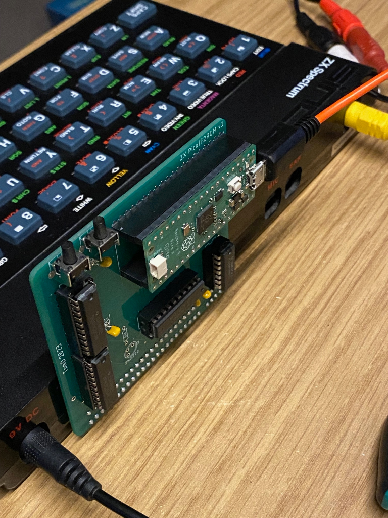
Have followed this thread and photo essay with great interest. Decided to re-build it as an excuse to learn how the PIO works on the PICO which removes the need to overclock. Anyway finally got it all working. I also shifted to using through hole components due to my less than stellar soldering skills.

I've started a GitHub to document my findings and put the code etc... https://github.com/TomDDG/ZXPicoIF2ROM

Image
Retro enthusiast and author of Flynn's Adventure in Bombland, The Order of Mazes & Maze Death Rally-X. Check them out at http://tomdalby.com
Post Reply