I've built a Spectrum 3b with all new parts and, of course, it doesn't work.
I'm checking voltages and the +5v and +12v is fine at all the ICs.
I'm testing voltages at the edge connector and I'm seeing 9v instead of -12v and -4.58v instead of -5v.
I've checked all the components in the schematic around the -ve voltage generation area (c47,c46, r54, r55, d11,d12,d16). I've got the right components but not sure how to test them attached to the board.
Any ideas what could be wrong? The 9v instead of -12v seems odd, maybe a short somewhere? Are there other places I can test -5v and -12v?
(I'm using the retroleum replacement upper & lower ram boards which don't use -ve voltages, perhaps this might affect my readings?)
thanks
Incorrect voltages on Spectrum 3b
-
MustardTiger

- Microbot
- Posts: 122
- Joined: Tue May 02, 2023 8:05 pm
Re: Incorrect voltages on Spectrum 3b
To clarify, do you mean you're getting +9V instead of -12V, or -9V instead of -12V?
-
MustardTiger
- Microbot
- Posts: 122
- Joined: Tue May 02, 2023 8:05 pm
-
MustardTiger
- Microbot
- Posts: 122
- Joined: Tue May 02, 2023 8:05 pm
Re: Incorrect voltages on Spectrum 3b
I think I broke TR5. TIme to order more parts...
Re: Incorrect voltages on Spectrum 3b
Sounds like some broken components if you're reading +9v on Pin1 of the 4116 sockets.
If you dont need the negative rail, then 12v is only needed for the video output circuit.
If you dont need the negative rail, then 12v is only needed for the video output circuit.
-
1024MAK

- Bugaboo
- Posts: 3123
- Joined: Wed Nov 15, 2017 2:52 pm
- Location: Sunny Somerset in the U.K. in Europe
Re: Incorrect voltages on Spectrum 3b
What -12V? The machine has no such rail. However, some documents misprint the ~ for a -.
The ~12V is actually the pluses from the DC/DC converter, hence is sometimes labelled 12V AC. but it’s not true AC. The multimeter will give a misleading value here, so please don’t worry about the voltage on the edge-connector pin 23 upper side.
The voltage on the -5V rail is controlled by the 5.1V zener diode and a series resistor (value and PCB reference depends on which revision of the circuit is being used). Sinclair went through at least two different designs for this part of the circuit. Hence this significantly affects the voltage on the -5V rail.
As you are not using this rail, and it’s within the -5.5V and -4V range given in the service manual, I would not worry about it.
Mark
“There are four lights!”
Step up to red alert. Sir, are you absolutely sure? It does mean changing the bulb
Looking forward to summer later in the year.
-
MustardTiger
- Microbot
- Posts: 122
- Joined: Tue May 02, 2023 8:05 pm
Re: Incorrect voltages on Spectrum 3b
I'm still trying to figure out why my speccy build doesn't work. Pretty sure I've blown an IC but I don't have spares to try.
At first I had lots of multicoloured attributes and started testing voltages. I think I shorted something as it all went black and it's been like this since. My TV just says 'no signal' (This is using a composite mod btw)
All the voltages check out all over the board.
I replaced the LM ic.
I swapped 74HCT157's around in case it was one of those
I checked the clk on the edge connector with my cheap £50 ebay oscilliscope (max500khz) and it had something going on. Not sure it was OK
The video signal at the modulator is a steady 1.8v whether that means anything.
I've done a diode check on all transistors and replaced a couple (TR4,5 & 3)
All resistors are OK.
Not sure how to test caps or whether they would have shorted!?
I'm using a vLA82 ULA replacement and the retroleum lower/upper ram boards. Is there any way of testing these are OK?
What can I test on the Z80 and would this even cause a black screen if it was faulty.
Thanks
-
1024MAK
- Bugaboo
- Posts: 3123
- Joined: Wed Nov 15, 2017 2:52 pm
- Location: Sunny Somerset in the U.K. in Europe
Re: Incorrect voltages on Spectrum 3b
Most likely that the vLA82 has been damaged.
You can remove all the RAM, ROM, Z80 and support logic chips and the ULA / vLA82 should still produce a picture, not a very useful picture, but still a border, and random rubbish in the central area, but non-the less, a picture.
Transistors (apart from in the DC/DC converter circuitry), resistors and capacitors generally are fairly rugged and a short duration short circuit is unlikely to blow them.
If the ULA/vLA82 is damaged, the Z80 will not have a clock, and hence won’t do anything useful.
Do you have a working board to test chips in?
Mark
“There are four lights!”
Step up to red alert. Sir, are you absolutely sure? It does mean changing the bulb
Looking forward to summer later in the year.
-
MustardTiger
- Microbot
- Posts: 122
- Joined: Tue May 02, 2023 8:05 pm
Re: Incorrect voltages on Spectrum 3b
Thanks Mark, that's really useful info.
I'll try removing all the chips except the vLA82 and look for a picture. I'm pretty sure it's broken though but I didn't want to just order another without knowing for sure, they're quite hard to find.
I'll test the z80 clock again after that.
I don't have another working board so I can't just swap chips around.
Thanks again
Re: Incorrect voltages on Spectrum 3b
Zx renew have some vLA82 in stock
https://zxrenew.co.uk/ZX-Spectrum-repla ... p151287223
https://zxrenew.co.uk/ZX-Spectrum-repla ... p151287223
-
MustardTiger
- Microbot
- Posts: 122
- Joined: Tue May 02, 2023 8:05 pm
Re: Incorrect voltages on Spectrum 3b
I've installed a new ULA and am back to corrupted colours.

The colours are always the same, no matter how many times I reboot which I suppose could be due to the lower ram board.
The border never goes white so the Z80 must not be running the ROM code.
A couple of questions I have as I try figure this out.
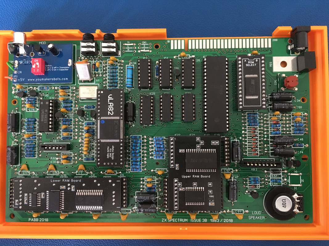
1. Here's a pic of my board.

https://i.postimg.cc/d3NYrgGw/IMG-1026.jpg
I used all 1% tolerance resistors assuming they would be fine. Was this a correct assumption?
2. TR6 was a BC337 but I changed that to a MPS2369 which turns out to be a PH2369. From what I can tell reading datasheets, this should be ok.
But did I orient it correctly? The schematics show the collector connected to the +5v and this seems to be the southern most pin when I check connectivity. Did I get this right?
The colours are always the same, no matter how many times I reboot which I suppose could be due to the lower ram board.
The border never goes white so the Z80 must not be running the ROM code.
A couple of questions I have as I try figure this out.
1. Here's a pic of my board.
https://i.postimg.cc/d3NYrgGw/IMG-1026.jpg
I used all 1% tolerance resistors assuming they would be fine. Was this a correct assumption?
2. TR6 was a BC337 but I changed that to a MPS2369 which turns out to be a PH2369. From what I can tell reading datasheets, this should be ok.
But did I orient it correctly? The schematics show the collector connected to the +5v and this seems to be the southern most pin when I check connectivity. Did I get this right?
-
1024MAK
- Bugaboo
- Posts: 3123
- Joined: Wed Nov 15, 2017 2:52 pm
- Location: Sunny Somerset in the U.K. in Europe
Re: Incorrect voltages on Spectrum 3b
Using 1% tolerance resistors is fine.
PH2369 should be okay. However, there is more than one case type used for some versions of the 2369. If it’s in the wrong way, it may not work correctly.
Can you take some close up photos of it on your board from different angles please.
Mark
PH2369 should be okay. However, there is more than one case type used for some versions of the 2369. If it’s in the wrong way, it may not work correctly.
Can you take some close up photos of it on your board from different angles please.
Mark
“There are four lights!”
Step up to red alert. Sir, are you absolutely sure? It does mean changing the bulb
Looking forward to summer later in the year.
-
MustardTiger
- Microbot
- Posts: 122
- Joined: Tue May 02, 2023 8:05 pm
Re: Incorrect voltages on Spectrum 3b
I can take more pictures, what are you wanting to see in more detail?
(not sure why postimages shrunk my board pic, here is another link to a higher res one https://postimg.cc/BPFkGYhV )
The transistor in TR6 has BR PH2369 E594 written on it. Flat side is facing west.
(not sure why postimages shrunk my board pic, here is another link to a higher res one https://postimg.cc/BPFkGYhV )
The transistor in TR6 has BR PH2369 E594 written on it. Flat side is facing west.
Last edited by MustardTiger on Tue Aug 22, 2023 10:50 pm, edited 1 time in total.
-
1024MAK
- Bugaboo
- Posts: 3123
- Joined: Wed Nov 15, 2017 2:52 pm
- Location: Sunny Somerset in the U.K. in Europe
Re: Incorrect voltages on Spectrum 3b
TR6…
“There are four lights!”
Step up to red alert. Sir, are you absolutely sure? It does mean changing the bulb
Looking forward to summer later in the year.
-
MustardTiger
- Microbot
- Posts: 122
- Joined: Tue May 02, 2023 8:05 pm
Re: Incorrect voltages on Spectrum 3b
I posted some pictures taken with my soldering microscope
https://postimg.cc/gallery/PL7X2nT
Thanks for looking.
https://postimg.cc/gallery/PL7X2nT
Thanks for looking.

Re: Incorrect voltages on Spectrum 3b
I think, you missed a connection from pin 1 to pin 28 at the ROM-socket. This connection is important because an EPROM is used instead of an ROM. I think you'll find any instructions for your "ROM-select", may be there is something to wire at the H/N connections wich is now soldered for Hitachi-ROM (H) ...
and by the way, make sure that the capacitors with their wires (C6 for example - there ist a point very close under the right wire - same C48) do not rest on "wrong" solder points
and by the way, make sure that the capacitors with their wires (C6 for example - there ist a point very close under the right wire - same C48) do not rest on "wrong" solder points
Last edited by Tiger on Wed Aug 23, 2023 9:14 am, edited 1 time in total.
Re: Incorrect voltages on Spectrum 3b
Your 2369's are mountet in the right way - looking from top there is (flat side down, round up) Emitter left, Base middle, Collector right.
-
MustardTiger
- Microbot
- Posts: 122
- Joined: Tue May 02, 2023 8:05 pm
Re: Incorrect voltages on Spectrum 3b
Thanks Tiger.
The instructions with the ROM states that no mods are needed unlike an EEPROM. It also states that the ROM selection links are irrelevant but I think I'll try swapping those around as mine are different to the LostRetroTapes video build.
Thanks for confirming the transistor orientation too.
The instructions with the ROM states that no mods are needed unlike an EEPROM. It also states that the ROM selection links are irrelevant but I think I'll try swapping those around as mine are different to the LostRetroTapes video build.
Thanks for confirming the transistor orientation too.
Re: Incorrect voltages on Spectrum 3b
Oh yes - I found it now at retroleum. I think you got the standard ROM in slot A and DiagROM in slot B. Your scrambled screen now looks for me as the DiagROM-Test screen  Maybe there is something wrong with the program of this little part...
R33 (680 Ohm) and R32 (100 Ohm) are ok? I remember of an 3b-Replika board with missing connection from R32 to pin 1 of IC 3 and IC4 ... Different screen if you solder the wires to N (NEC-ROM)? At last the CPU could be faulty ...
R33 (680 Ohm) and R32 (100 Ohm) are ok? I remember of an 3b-Replika board with missing connection from R32 to pin 1 of IC 3 and IC4
Re: Incorrect voltages on Spectrum 3b
I've just read your discussion from the beginning and you wrote that there was a black screen first.  I got one vLA82 from Charlie in the past wich also "produced" a completely black screen. I had a spare board where I was able to swap the ULA and could locate the faulty vLA. Charlie was so kind to test it (the CPLD has failed) and send an replacement. Charlie is very helpful and I think if you ask him for a replacement he will tell you how to do ... (by the way: I waited more than 2 month - New Zealand is far away
  )
)
-
MustardTiger
- Microbot
- Posts: 122
- Joined: Tue May 02, 2023 8:05 pm
Re: Incorrect voltages on Spectrum 3b
My first vLA did work until I started testing voltages and shorted something.  I waited a while for a UK supplier to get new stock.
Both the rom settings have the scrambled screen, I don't think the z80 is executing any code as the border stays black.
The scrambled screen does look similar to the diag rom, but looking at videos on youtube there should be some other onscreen menues before the scrambled image. Also, my scrambled image has the black/white stripes faintly in the background.
Thanks for the suggestions.
-
MustardTiger
- Microbot
- Posts: 122
- Joined: Tue May 02, 2023 8:05 pm
Re: Incorrect voltages on Spectrum 3b
Tried lots of things
Replaced TR3, was a 2n4401 but now a ph2369. Datasheet suggests the switching times are OK.
Replaced z80
Changed rom link settings (although I still got the same coloured squares with no links installed, maybe this doesn't affect the retroleum rom)
Checked R32 connections to IC3&4, OK
Checked all address lines and data lines connections, all OK
What I need to do is check the z80 is getting a clk. My oscilloscope is a cheap ebay one which doesn't go to 3.5mhz but maybe that doesn't matter, as long as I see some kind of pulsing? Also last time I was tinkering with the power on I shorted my ULA out.
What confuses me the most is the coloured blocks are always identical, exactly the same colours/flashing in the same positions.
-
MustardTiger
- Microbot
- Posts: 122
- Joined: Tue May 02, 2023 8:05 pm
Re: Incorrect voltages on Spectrum 3b
I got hold of a proper oscilloscope and checked the clock on the Z80 (pin6). I'm getting 3.5mhz but min voltage is 4.3v and max is 5.0v. This must be wrong, I'd expect the minimum to be much lower.
What could cause the lower voltage to remain so high?
What could cause the lower voltage to remain so high?
-
1024MAK
- Bugaboo
- Posts: 3123
- Joined: Wed Nov 15, 2017 2:52 pm
- Location: Sunny Somerset in the U.K. in Europe
Re: Incorrect voltages on Spectrum 3b
What is the output signal from the ULA / vLA like? Test on resistor R24 (right hand lead according to the schematic but please check).
You can test the clock signal to the Z80 on resistor R25 (left hand lead according to the schematic but please check).
Is capacitor C67 fitted? What are the values of R24 and R25?
Is your ‘scope a single channel or a dual channel type? If it’s a dual channel type and you have ‘scope probe clips, you can monitor two signals at the same time. Use a single 0V/GND point for both though.
TR3 HAS to have a fast turn off time, otherwise it’s collector will never go low. What transistor was fitted originally? Or had someone else changed it?
Sinclair used ZTX313 type for a reason. They are very fast at switching off.
Most general purpose transistors will NOT work in this position.
The Z80 won’t operate unless the clock signal is within specification (low is below 0.45V, high is at least VCC-0.6V). This is far more critical than any other input pin on it.
Mark
“There are four lights!”
Step up to red alert. Sir, are you absolutely sure? It does mean changing the bulb
Looking forward to summer later in the year.
-
MustardTiger
- Microbot
- Posts: 122
- Joined: Tue May 02, 2023 8:05 pm
Re: Incorrect voltages on Spectrum 3b
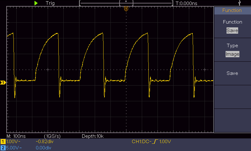
This is the output from the vLA at R24 right. vb=140mv vt 3.18v 3.5mhz
This is the output from R25 left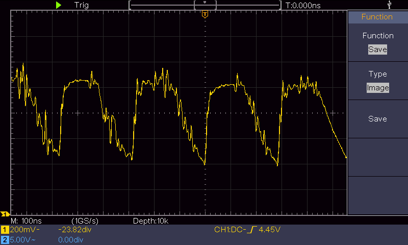 with the voltages mentioned in my previous post (Bit annoying the scope doesn't save the measurement info to the screen save)
R24 is 1 1K0 (but reads 840ohms on the multimeter, I guess due to being in-circuit?)
R25 is 180r and measures 180r
C67 is 101 (100pf)
Given the scope image for the Z80 clock does it look like the switch off time might be a problem? Or is it the capacitor? I'm using a PH2369 which has a turn off time of 20ns or 35ns according to the datasheet. MPS2369 is suggested as a replacement for ZTX313 in the service manual, that has a turn off time of 10ns-18ns.
There never was an original transistor as this is a completely new build.
This is the output from R25 left
with the voltages mentioned in my previous post (Bit annoying the scope doesn't save the measurement info to the screen save)R24 is 1 1K0 (but reads 840ohms on the multimeter, I guess due to being in-circuit?)
R25 is 180r and measures 180r
C67 is 101 (100pf)
Given the scope image for the Z80 clock does it look like the switch off time might be a problem? Or is it the capacitor? I'm using a PH2369 which has a turn off time of 20ns or 35ns according to the datasheet. MPS2369 is suggested as a replacement for ZTX313 in the service manual, that has a turn off time of 10ns-18ns.
There never was an original transistor as this is a completely new build.