Incorrect voltages on Spectrum 3b

For experts to discuss very technical stuff and newbies to ask why the Spectrum they bought off ebay doesn't work.
User avatar
1024MAK
Bugaboo
Posts: 3123
Joined: Wed Nov 15, 2017 2:52 pm
Location: Sunny Somerset in the U.K. in Europe

Re: Incorrect voltages on Spectrum 3b

Post by 1024MAK »

Sorry, I forgot your’s was a new build! :oops:

Trying to do too many things, including helping others fault find existing (old) boards…

When looking at digital waveforms, I normally make the following recommendations:
  • For high speed signals, use a X10 scope probe (and calibrate it using the test signal available on many scopes by adjusting the adjustment trimmer for the best waveform, that is minimum overshoot/undershoot and the best square wave),
  • Show on the screenshot or photo where 0V/GND is in relation to the displayed waveform.. If possible mark the volts per division as well as the voltage measured by the scope.
  • Use a good 0V/GND point for all the ‘scope probes.
Actually now that I can see the waveform, it looks like TR3 is not switching on hard enough. The collector voltage (R25) voltage should get to be very close (less than 0.2V) to 0V when it’s switched on (input voltage is high).

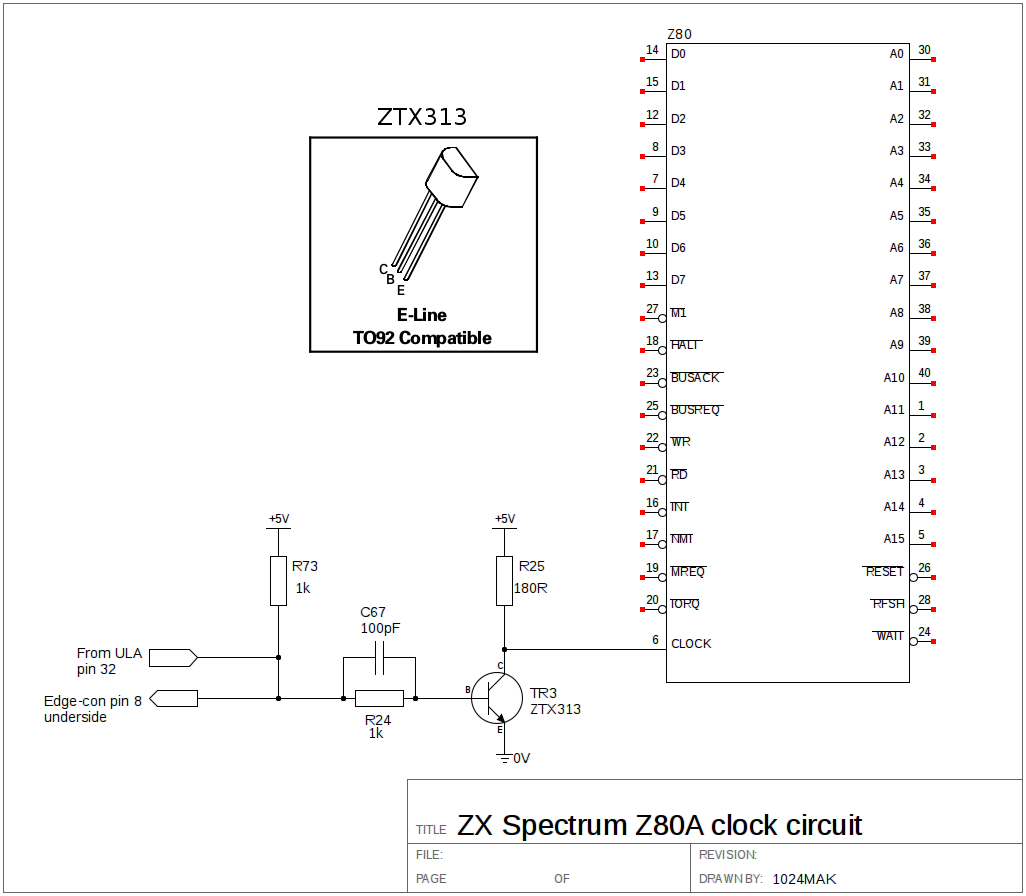
Can you please double check that it’s fitted the correct way round.

By the way, the purpose of C67 is to try to speed up switching on and off.

If TR3 is fitted correctly, the options as I see it are:
  • Try another PH2369
  • Try a lower resistor for R24. However, a 1kΩ should be fine for this design.
  • Try a different transistor.
The only other thing I can think of, is a PCB track problem or a poor solder joint.

The selection of the resistor is a compromise, a lower value increases the base current and turns the transistor on harder, it also which increases the saturation of the junction, which in turn increases the amount of time it takes to turn off.
A higher value reduces the amount of current to the base of the transistor, which means it’s junction is less saturated, so it should turn off quicker. But you still need enough current to turn the transistor fully on so that the collector goes to near 0V/GND.

Mark
:!: Standby alert :!:
“There are four lights!”
Step up to red alert. Sir, are you absolutely sure? It does mean changing the bulb :dance
Looking forward to summer later in the year.
User avatar
MustardTiger
Microbot
Posts: 122
Joined: Tue May 02, 2023 8:05 pm

Re: Incorrect voltages on Spectrum 3b

Post by MustardTiger »

I've replaced TR3 with a ZTX313 and the waveform is better but varies between 4.5v and 5v which is incorrect, with a very short spike to 0v. (measured on R25 left)

I replaced C67 with another 100pf (different batch from before) but same problem. R24 and R25 measure OK.

What would cause me to get 4.5v rather than 0v from the transistor emitter? I've checked for shorts and found nothing but I'm going to check again tomorrow.

(I actually replaced TR3 with a socket so I can test different transistors and orientations. An MPS2369 had a better waveform than the PH2369 but still had the same min voltage as 4.5v.
User avatar
1024MAK
Bugaboo
Posts: 3123
Joined: Wed Nov 15, 2017 2:52 pm
Location: Sunny Somerset in the U.K. in Europe

Re: Incorrect voltages on Spectrum 3b

Post by 1024MAK »

Here's a simplified schematic of just the clock circuitry:
Image
Image

Mark
:!: Standby alert :!:
“There are four lights!”
Step up to red alert. Sir, are you absolutely sure? It does mean changing the bulb :dance
Looking forward to summer later in the year.
User avatar
MustardTiger
Microbot
Posts: 122
Joined: Tue May 02, 2023 8:05 pm

Re: Incorrect voltages on Spectrum 3b

Post by MustardTiger »

Thanks for the diagram, thats clearer than the schematics.

I woke up this morning thinking that the emitter connected to 0v must be getting 4.5v from somewhere, a splash of solder or faulty pcb, as the clock signal is squareish in the scope shows the transistor is working. Now the transistor is in a temporary socket I can jump the emiiter to a definite gnd and see what the results are.
User avatar
1024MAK
Bugaboo
Posts: 3123
Joined: Wed Nov 15, 2017 2:52 pm
Location: Sunny Somerset in the U.K. in Europe

Re: Incorrect voltages on Spectrum 3b

Post by 1024MAK »

Having thought about this overnight, one possibility is that part of the clock line is shorted to another signal / PCB track. Carefully inspect the board looking for a short circuit, especially look for solder splashes, do this for all of the circuit, both the ULA pin 32 side, the TR3 part and the Z80 pin 6 part. Solder splashes can be as thin as a human hair.

The other possibilities are that the transistor emitter (e) is not actually connected to the 0V/GND rail, maybe due to a PCB fault. That’s easy to test. with the power off, measure between the transistor emitter (e) and the 0V/GND rail at the voltage regulator (middle pin). It should be less than 1Ω (not including the resistance of the meter leads).

Also with the ULA, Z80 and TR3 removed, using the continuity range/mode, trace out the circuit to confirm each PCB track goes where it should. Then using the 20kΩ or 200kΩ resistance range, test each part of the clock circuit to any and all adjacent PCB tracks to check for short circuits.

If none of this finds the problem, with ULA, Z80 and TR3 still removed, power up the board and measure the voltages at all three of the transistors terminals, ULA pin 32 and Z80 pin 6, Then, switch to the 200mA current range on your multimeter. Connect it between the Z80 pin 6 and the transistor emitter (e) terminal. 27.7mA should be the displayed current. Disconnect and switch back to voltage/reconfigure to voltage.

Power down. Refit ONLY TR3. Connect the meter to measure voltage between Z80 pin 6 and any convenient 0V/GND rail point (but NOT TR3 emitter). Power back up. What voltage do you have? Now using a suitable test lead or piece of thin solid core wire, connect ULA pin 40 to ULA pin 32. What voltage do you have now on pin 6 of the Z80? Then connect ULA pin 14 to ULA pin 32. What voltage do you have now on pin 6 of the Z80?

Report back your results.

Mark
:!: Standby alert :!:
“There are four lights!”
Step up to red alert. Sir, are you absolutely sure? It does mean changing the bulb :dance
Looking forward to summer later in the year.
User avatar
MustardTiger
Microbot
Posts: 122
Joined: Tue May 02, 2023 8:05 pm

Re: Incorrect voltages on Spectrum 3b

Post by MustardTiger »

I'm done with this.

Plugged the z80/ula back in and no picture again, just a whistling noise.

I've got all the anti static protection but it seems like the vla82 has gone again. Those things are flaky af.

Thanks for all the help, but I can't be bothered with this anymore.
User avatar
MustardTiger
Microbot
Posts: 122
Joined: Tue May 02, 2023 8:05 pm

Re: Incorrect voltages on Spectrum 3b

Post by MustardTiger »

1024MAK wrote: Thu Sep 21, 2023 8:04 am
If none of this finds the problem, with ULA, Z80 and TR3 still removed, power up the board and measure the voltages at all three of the transistors terminals, ULA pin 32 and Z80 pin 6, Then, switch to the 200mA current range on your multimeter. Connect it between the Z80 pin 6 and the transistor emitter (e) terminal. 27.7mA should be the displayed current. Disconnect and switch back to voltage/reconfigure to voltage.

Power down. Refit ONLY TR3. Connect the meter to measure voltage between Z80 pin 6 and any convenient 0V/GND rail point (but NOT TR3 emitter). Power back up. What voltage do you have? Now using a suitable test lead or piece of thin solid core wire, connect ULA pin 40 to ULA pin 32. What voltage do you have now on pin 6 of the Z80? Then connect ULA pin 14 to ULA pin 32. What voltage do you have now on pin 6 of the Z80?

Mark
Hi Mark, I'm revisiting this old, old problem, I built a harlequin over xmas and it fired up first time so the amount of trouble I've had with this build is baffling :lol:

Could you list the voltages I should be expecting from you comment above?

I tested Z80 pin 6 and ULA pin 40 without TR3 and got ~4.95v. With TR3 ULA pin 40 was 2.87v and Z80 pin6 was 0.2v

Thanks

Pete
User avatar
1024MAK
Bugaboo
Posts: 3123
Joined: Wed Nov 15, 2017 2:52 pm
Location: Sunny Somerset in the U.K. in Europe

Re: Incorrect voltages on Spectrum 3b

Post by 1024MAK »

Note, where I quote 5V, this is assuming your VCC / +5V rail is exactly 5V. So if this rail is 4.9V and you get 4.9V where I state 5V, that's fine.

With TR3 removed, the ULA and Z80 not fitted:

ULA pin 32 = 5V
Z80 pin 6 = 5V
TR3 base = 5V
TR3 collector = 5V
TR3 emitter = 0V

Current test (between the Z80 pin 6 and the transistor emitter) = 27.7mA

With TR3 fitted, but the ULA and Z80 not fitted:

ULA pin 32 = approx 2.8V to 2.9V
Z80 pin 6 = 0V
TR3 base = approx 550 to 700mV
TR3 collector = 0V

With ULA pin 40 connected to ULA pin 32:

Z80 pin 6 = 5V

With ULA pin 14 connected to ULA pin 32:

Z80 pin 6 = 0V

Mark
:!: Standby alert :!:
“There are four lights!”
Step up to red alert. Sir, are you absolutely sure? It does mean changing the bulb :dance
Looking forward to summer later in the year.
User avatar
MustardTiger
Microbot
Posts: 122
Joined: Tue May 02, 2023 8:05 pm

Re: Incorrect voltages on Spectrum 3b

Post by MustardTiger »

Thanks for the checklist. Checked all those voltages and currents and they match. 0v was about 0.2v but that's probably fine.

Without the Z80 and ULA, I measured the V on the A0-A15 and D0-D7. A lines were all 0v on the Z80 and ~3.6v on the ULA. All the D lines were 4.9v. The KB lines on the ULA were all 4.9v too. Does that sound correct?
User avatar
1024MAK
Bugaboo
Posts: 3123
Joined: Wed Nov 15, 2017 2:52 pm
Location: Sunny Somerset in the U.K. in Europe

Re: Incorrect voltages on Spectrum 3b

Post by 1024MAK »

The data lines and the keyboard input lines to the ULA are all pulled high by resistors, so yes, without anything to drive them, they should be around VCC (+5V).

Which address lines on the ULA socket did you test? IC3 and IC4 will affect A0 to A6. A14 and A15 should be the same level as on the Z80 socket.

Mark
:!: Standby alert :!:
“There are four lights!”
Step up to red alert. Sir, are you absolutely sure? It does mean changing the bulb :dance
Looking forward to summer later in the year.
User avatar
MustardTiger
Microbot
Posts: 122
Joined: Tue May 02, 2023 8:05 pm

Re: Incorrect voltages on Spectrum 3b

Post by MustardTiger »

ULA A14-15 are the same as the Z80, ~0v

ULA A0-A6 are ~3.6v
Post Reply