Spectrum 128k IC6 & IC17 connections

For experts to discuss very technical stuff and newbies to ask why the Spectrum they bought off ebay doesn't work.
Post Reply
KeplerOfMars
Drutt
Posts: 45
Joined: Mon Jun 26, 2023 6:23 pm

Spectrum 128k IC6 & IC17 connections

Post by KeplerOfMars »

Hello,

Could some kind soul explain which pins on IC6 should be connected to IC17 (the 4164 to its immediate right). I have had a look at the schematic but it is not clear to me.

Image

Thanks.
Waldroid
Microbot
Posts: 121
Joined: Tue May 30, 2023 6:52 pm

Re: Spectrum 128k IC6 & IC17 connections

Post by Waldroid »

Erm, well, none really. (Except for GND and +5V, I maybe.)

IC6 is in the contended RAM (equivalent to the lower RAM on a 48k Spectrum), and IC17 is in the uncontended RAM (equivalent to the upper RAM on a 48k).
KeplerOfMars
Drutt
Posts: 45
Joined: Mon Jun 26, 2023 6:23 pm

Re: Spectrum 128k IC6 & IC17 connections

Post by KeplerOfMars »

That's good as I have connectivity between those on pins 8 & 16.
I know this is a proverbial "stab in the dark" but I am attempting to determine if my socketing of all the RAM ICs have caused my 128 to stop booting.
All the ICs have connectivity to the IC on the right with their corresponding pins except on 1,2 & 14 - the exception to this is between IC18 - IC19 where there is connectivity on all the pins except pin 1.
User avatar
1024MAK
Bugaboo
Posts: 3171
Joined: Wed Nov 15, 2017 2:52 pm
Location: Sunny Somerset in the U.K. in Europe

Re: Spectrum 128k IC6 & IC17 connections

Post by 1024MAK »

A 4164 DRAM
Image

Pin 1 is not connected (no connection) as it’s not used.
Pin 2 is data in. In most applications, this is linked to pin 14. This goes to one of the data bus lines. Eight data lines, hence eight DRAM chips (because each DRAM chip only handles one bit of each byte).
Pin 8 is the +5V supply
Pin 16 is the 0V/GND

All the other pins will be linked to the other seven chips in the same group of eight chips (each chip wired in parallel).

The pins prefixed ‘A’ are the multiplexed address inputs.
The remaining three pins (3, 4 & 15) are the control pins.

Mark
:!: Standby alert :!:
“There are four lights!”
Step up to red alert. Sir, are you absolutely sure? It does mean changing the bulb :dance
Looking forward to summer being good this year.
KeplerOfMars
Drutt
Posts: 45
Joined: Mon Jun 26, 2023 6:23 pm

Re: Spectrum 128k IC6 & IC17 connections

Post by KeplerOfMars »

Thank you Mark.

I checked the connections between all the RAM ICs and they are as expected. I did however find connectivity between IC18 & IC19 on pin 2 (blue dots) :

Image

Those vias terminate under a group text of resistors and there seems to be a connection to two resistors as there is connectivity from pin 2 on each of those ICs to a resistor on the top side (blue dots) :

Image

This may of course be completely correct but it would be useful to eliminate.

Thanks.
User avatar
1024MAK
Bugaboo
Posts: 3171
Joined: Wed Nov 15, 2017 2:52 pm
Location: Sunny Somerset in the U.K. in Europe

Re: Spectrum 128k IC6 & IC17 connections

Post by 1024MAK »

There will be connections to resistors, as Sinclair uses them to separate the data bus for the ULA and the Z80. These are R1 to R8.

But, unless something is faulty or there is a short circuit, there should not be continuity between different data bus lines. And from what you are describing, it sounds like this is what you have.

What results do you get when you test using the resistance range on your multimeter?

Another test you can do is to test between pins 8 (D3) and 7 (D4) on the Z80.

Mark
:!: Standby alert :!:
“There are four lights!”
Step up to red alert. Sir, are you absolutely sure? It does mean changing the bulb :dance
Looking forward to summer being good this year.
KeplerOfMars
Drutt
Posts: 45
Joined: Mon Jun 26, 2023 6:23 pm

Re: Spectrum 128k IC6 & IC17 connections

Post by KeplerOfMars »

I definitely have continuity between pin 2 on IC18 & pin 2 on IC19.
With resistance set at 2k on my meter, the reading very briefly shows a value around 0.5 and drops to 0.0.
There is also conductivity between pins 7 & 8 on the Z80.

IC32: there is conductivity between pins 7 and 8 of the Z80 with both pin 24 & pin 25 of 8912A - which I assume is not correct either?
User avatar
1024MAK
Bugaboo
Posts: 3171
Joined: Wed Nov 15, 2017 2:52 pm
Location: Sunny Somerset in the U.K. in Europe

Re: Spectrum 128k IC6 & IC17 connections

Post by 1024MAK »

Does your multimeter have a 200Ω resistance range? That’s the range I recommend when testing for short circuits.

Yes, on any chip that has connections to the data bus on the Z80 side, you will see the same short circuit.

Do you know what work has been carried out on this board? Have any chips (other than the DRAM) been replaced or sockets provided? If someone else other than you did some work, this may be shown up by brown flux in and around the solder joints for example.

Mark
:!: Standby alert :!:
“There are four lights!”
Step up to red alert. Sir, are you absolutely sure? It does mean changing the bulb :dance
Looking forward to summer being good this year.
KeplerOfMars
Drutt
Posts: 45
Joined: Mon Jun 26, 2023 6:23 pm

Re: Spectrum 128k IC6 & IC17 connections

Post by KeplerOfMars »

Yes, the 200 Ohm is shared with the conductivity option. The meter registers 0.03 when testing between pin 2 on IC18 & 19.

No other work has been done other than the socketed RAM ICs that I am aware of. If it helps, I have removed IC32 and IC31, the short on pins 7 & 8 of the Z80 remains.
KeplerOfMars
Drutt
Posts: 45
Joined: Mon Jun 26, 2023 6:23 pm

Re: Spectrum 128k IC6 & IC17 connections

Post by KeplerOfMars »

Update:

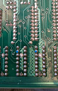
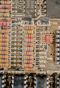
I finally found the cause of the short...a tiny piece of solder that had wedged itself between two traces under a RAM socket...I discovered this after desoldering several sockets. That is the good news...

The bad is that my Toastrack has now devolved into a standard 48k Spectrum!

Image

At first I couldn't quite believe it...but after a few resets...it was true.

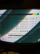
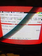
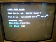
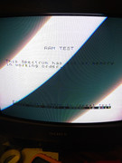
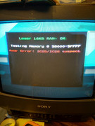
I then started running some diagnostics and found the following:

Image

Image

Image

Image

Image

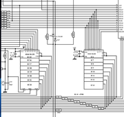
I then swapped IC15 & IC16 - no difference.
I then socketed both 74LS ICs and tried different ones - no difference.
I then checked for continuity between the two 74LS ICs and their end points - no broken traces.
I then checked continuity between the RAM ICs - nothing broken.

Now I am stuck...can anyone suggest what I could do next?!
Post Reply